Mixers for immiscible fluids

a technology of immiscible fluids and mixers, which is applied in the direction of mixing, transportation and packaging, chemical instruments and processes, etc., can solve the problems of immiscibility of hydrocarbon fuel oil and water, increase the complexity and cost of engine maintenance, and nitrogen oxide production, so as to improve the turbulent mixing of fluids, enhance the effect of fluid introduction, and reduce the loss of pressur

Active Publication Date: 2015-03-03
COLLINS ENGINE NOZZLES INC
View PDF15 Cites 0 Cited by
  • Summary
  • Abstract
  • Description
  • Claims
  • Application Information

AI Technical Summary

Benefits of technology

[0009]In certain embodiments, the mixer also includes a mixer section having a flow constriction defined in a downstream portion of the flow passage with a flow area smaller than that of the upstream portion of the flow passage for enhancing turbulent mixing of fluids introduced at the first and second fluid inlets. The flow area of the flow constriction can define a centerline axis that is offset with respect to the main longitudinal axis of the flow passage. The mixer section can include two or more flow constrictions, wherein each flow constriction defines a centerline axis that is offset with respect to the centerline axis of the other flow constriction. Each flow constriction can be offset with respect to the main longitudinal axis of the flow passage. It is also contemplated that the centerline axis of each flow constriction can be offset in a direction opposite that of the centerline axis of the other flow constriction with respect to the main longitudinal axis of the flow passage.
[0010]In certain embodiments, an upstream one of two flow constrictions includes a beveled upstream inlet and a beveled downstream outlet to form a converging, diverging flow path therethrough for reducing pressure loss. Bevel features, chamfers, or filet radius features can be included on either or all flow constrictions. A downstream one of two flow constrictions can include opposed upstream and downstream faces that are oriented substantially perpendicular to the main longitudinal axis. The two flow constrictions can be separated by a spin chamber defined in the flow passage of the mixer housing, and the spin chamber can have a flow area substantially equal in size with that of the upstream portion of the flow passage.
[0011]The outlet of the mixer housing can define an outlet axis that is substantially concentric with the main longitudinal axis of the flow passage. It is also contemplated that the secondary axis defined by the second fluid inlet can be oriented substantially perpendicular, or on any other suitable angle, and offset with respect to the main longitudinal axis of the flow passage. The mixer can further include an outlet conduit mounted in fluid communication with the outlet of the mixer housing, wherein the outlet conduit includes a bend therein to promote mixing of fluids introduced in the first and second fluid inlets.
[0012]The invention also provides a mixer for mixing immiscible fluids wherein the second fluid inlet is defined in the mixer housing downstream of the first fluid inlet in fluid communication with the upstream portion of the flow passage, and a mixer section including a pair of flow constrictions is defined in a downstream portion of the flow passage. The flow constrictions each have a flow area smaller than that of the upstream portion of the flow passage for enhancing turbulent mixing of fluids introduced at the first and second fluid inlets. Each flow constriction defines a centerline axis that is offset with respect to the centerline axis of the other flow constriction.
[0013]The invention also provides a mixer for mixing immiscible fluids in which the second fluid inlet includes a swirl inducer. A mixer housing defines a flow passage therethrough from a first fluid inlet to an outlet thereof. The flow passage defines a main longitudinal axis. A second fluid inlet is defined in the mixer housing downstream of the first fluid inlet in fluid communication with the flow passage and oriented at an angle with respect to the main longitudinal axis. The second fluid inlet includes a swirl inducer for inducing swirl on fluids flowing through the flow passage. A flow constriction is defined in the flow passage downstream of the second fluid inlet having a flow area smaller than that of the flow passage upstream thereof for accelerating a swirling flow of fluids flowing through the flow passage to enhance turbulent mixing of fluids introduced at the first and second fluid inlets.

Problems solved by technology

However, high temperature combustion also tends to increase the production of nitrogen oxides (NOX).
Injecting water into the combustor of a gas turbine engine presents challenges related to uniform distribution of water and fuel within the combustor.
These approaches attempt to provide uniform spray patterns of both fuel and water within the combustor, but add to the complexity and cost of the engine and maintenance.
The problem with this approach is that hydrocarbon fuel oil and water are immiscible.
Simply mingling the two fluids together in a fuel line does not result in a uniform distribution of the fuel-water mixture at the injectors, since the two fluids tend to arrive at the injectors in a highly unmixed state.

Method used


Image

  • Mixers for immiscible fluids
  • Mixers for immiscible fluids
  • Mixers for immiscible fluids

Examples


Embodiment Construction

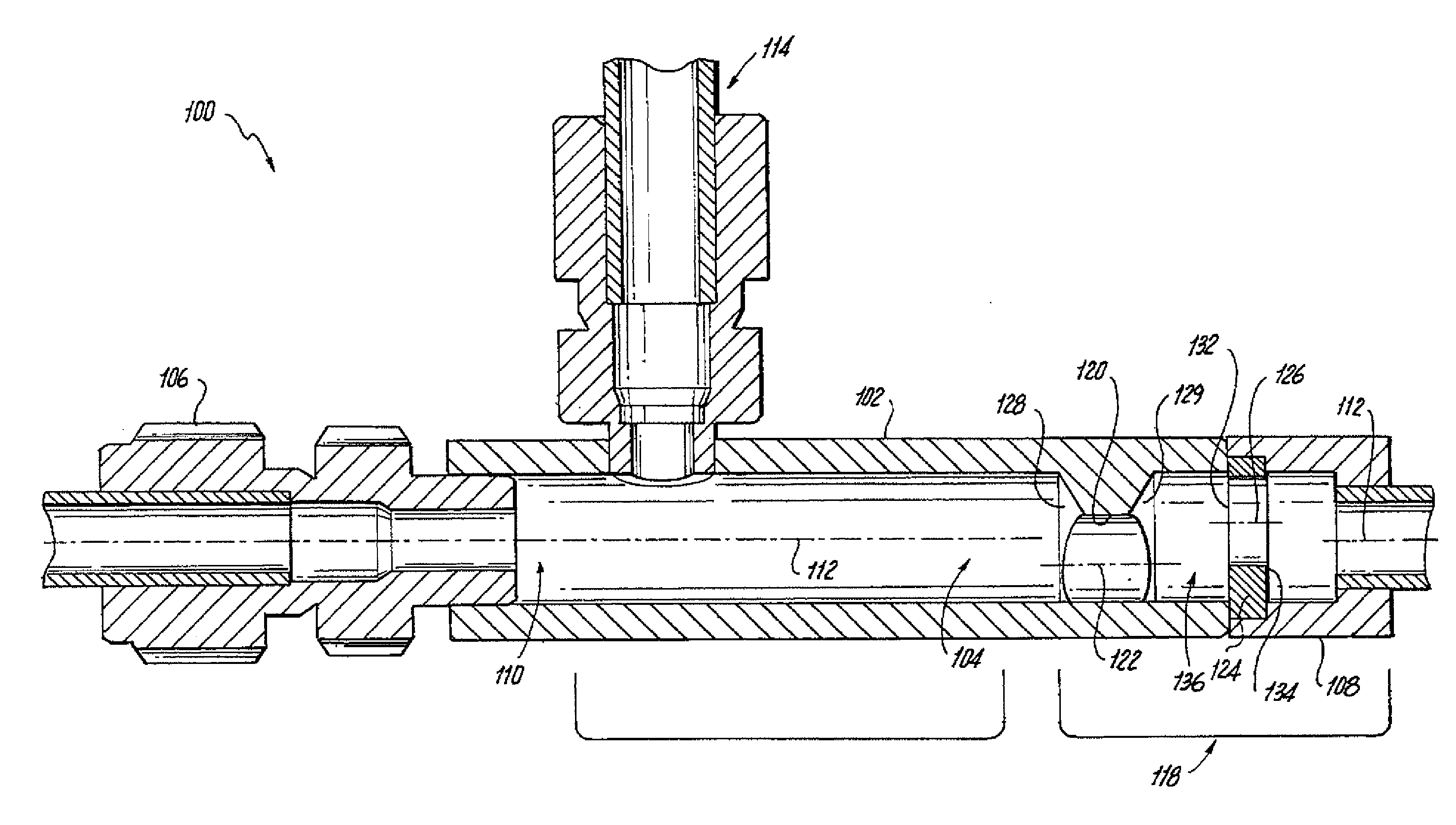
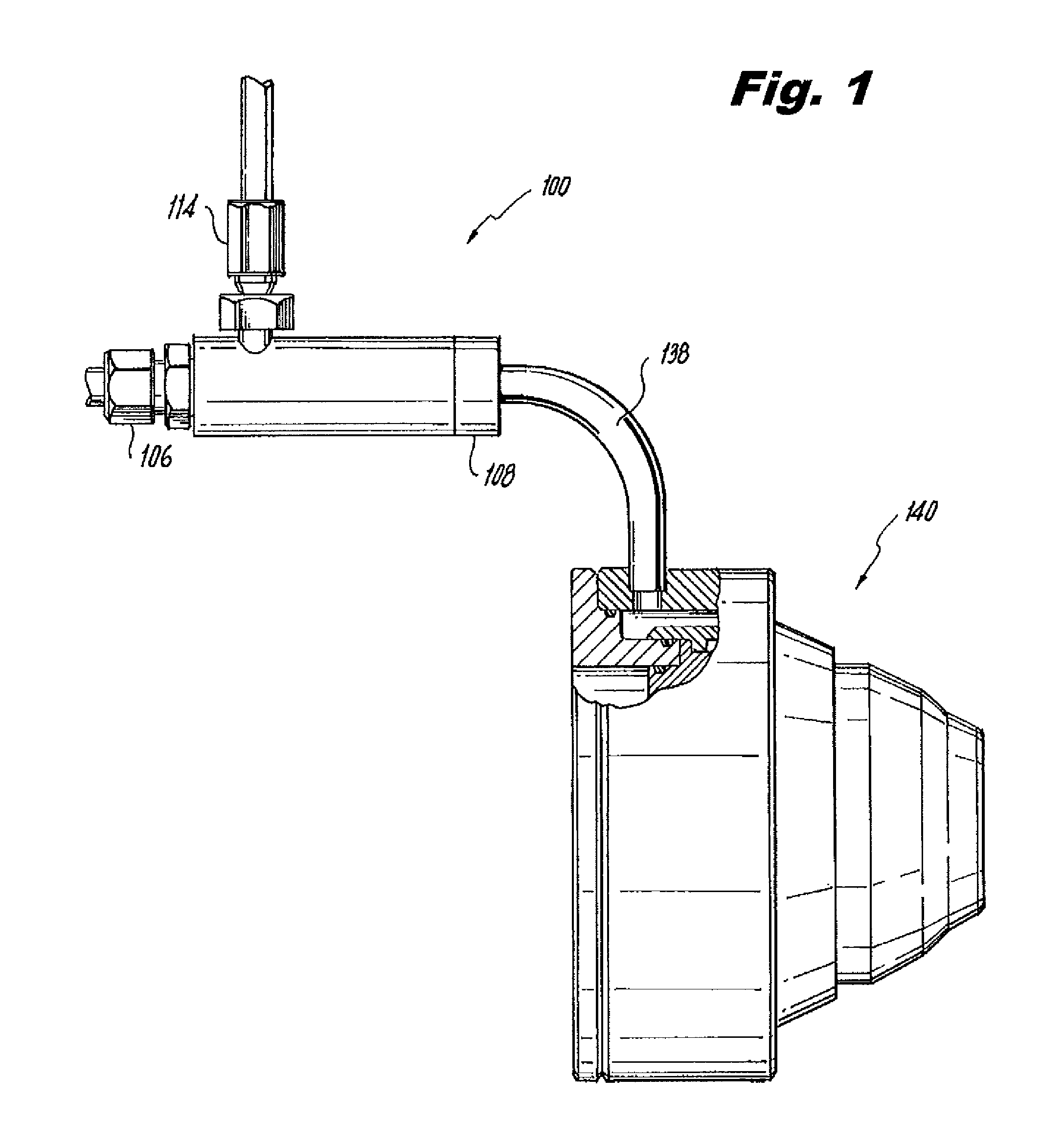
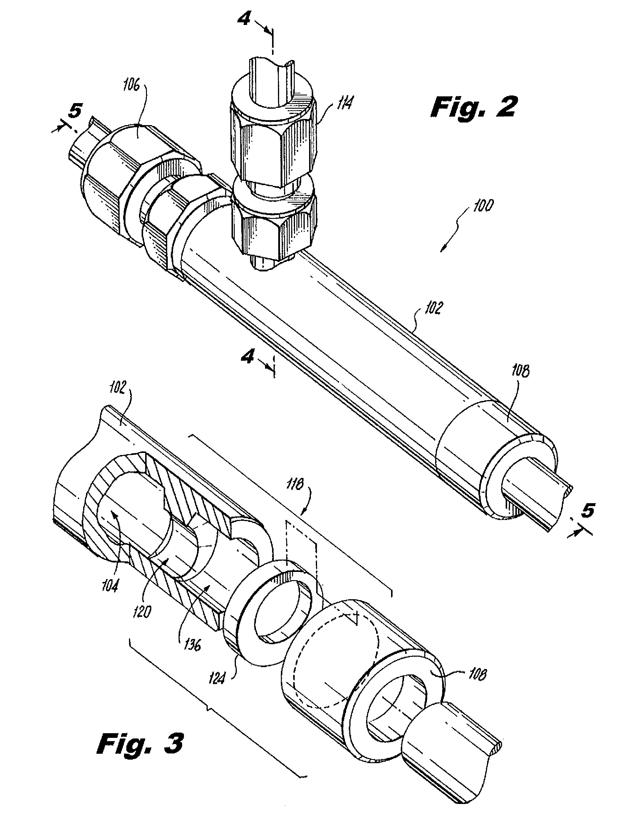
[0033]Reference will now be made to the drawings wherein like reference numerals identify similar structural features or aspects of the subject invention. For purposes of explanation and illustration, and not limitation, a partial view of an exemplary embodiment of a mixer in accordance with the invention is shown in FIG. 1 and is designated generally by reference character 100. Other embodiments of mixers in accordance with the invention, or aspects thereof, are provided in FIGS. 2-15, as will be described. The systems of the invention can be used to mix fluids together, including immiscible fluids, for example for delivering a water / fuel oil emulsion to a fuel nozzle for a low NOX gas turbine combustion system.

[0034]Referring now to FIGS. 1-2, mixer 100 has two inlets 106, 114 for receiving two different fluids, for example water and fuel, respectively. While discussed herein in the exemplary context of inlet 106 being used for water and inlet 114 being used for fuel, those skille...


PUM

PropertyMeasurementUnit
volume fractionaaaaaaaaaa
pressure lossaaaaaaaaaa

Abstract

A mixer for mixing immiscible fluids includes a mixer housing defining a flow passage therethrough from a first fluid inlet to an outlet thereof. An upstream portion of the flow passage defines a main longitudinal axis. A second fluid inlet is provided downstream of the first fluid inlet in fluid communication with the upstream portion of the flow passage. The second fluid inlet is offset with respect to the main longitudinal axis of the flow passage to introduce fluid along a path that is offset with respect to the main longitudinal axis for inducing swirl on fluids introduced at the first and second fluid inlets. In certain embodiments, a mixer section is included having a flow constriction defined in a downstream portion of the flow passage with a flow area smaller than that of the upstream portion of the flow passage for enhancing turbulent mixing of fluids therein.

Description

BACKGROUND OF THE INVENTION[0001]1. Field of the Invention[0002]The present invention relates to mixers for immiscible fluids, and more particularly to mixers for mixing fuel and water in gas turbine engines.[0003]2. Description of Related Art[0004]A variety of devices and methods are known in the art for injecting fuel into gas turbine engines. Of such devices, many are directed to injecting fuel into combustors of gas turbine engines while reducing undesirable emissions. Modern gas turbine engine designs use high temperature combustion for thermal efficiency throughout a range of engine operating conditions. High temperature combustion minimizes emissions of some undesired gaseous combustion products, such as carbon monoxide (CO) and unburned hydrocarbons (UHC), and particulates, among other things. However, high temperature combustion also tends to increase the production of nitrogen oxides (NOX). Thus measures must be taken to provide thermally efficient operation within a tempe...

Claims


Application Information

Patent Timeline
Patent Type & Authority Patents(United States)
IPC IPC(8): B01F5/06B01F3/08B01F5/00B01F5/04
CPCB01F5/0065B01F3/0807B01F5/0473B01F5/048B01F5/0608B01F2003/0842B01F23/4145B01F23/41B01F25/103B01F25/31423B01F25/3141B01F25/4233B01F25/27
Inventor PACK, SPENCER D.SMITH, STEVEN L.
Owner COLLINS ENGINE NOZZLES INC
Why Eureka
Try Eureka