A three-stage burn-off air arrangement
A technology of burn-out air and separation of burn-out air, applied in combustion equipment, lighting and heating equipment, etc., can solve the problems of expensive investment and operation and maintenance costs, eliminate the residual swirl intensity of flue gas, improve combustion efficiency, realize The effect of low NOx emissions
- Summary
- Abstract
- Description
- Claims
- Application Information
AI Technical Summary
Problems solved by technology
Method used
Image
Examples
Embodiment 1
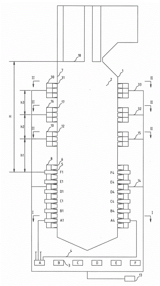
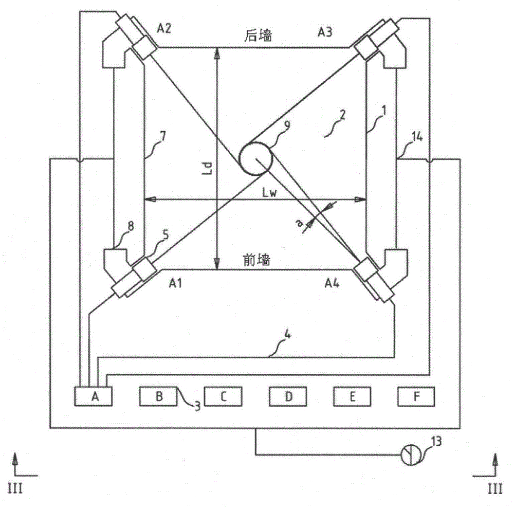
[0033] combine figure 2 , image 3 with Figure 4 To describe this embodiment, image 3 for figure 2 The Ⅰ-Ⅰ sectional view of Figure 4 for figure 2 The Ⅱ-Ⅱ sectional view of figure 2 for image 3 with Figure 4 Sectional view of III-III.
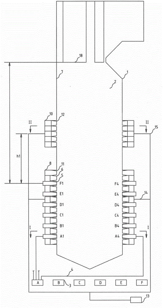
[0034] A three-stage burn-off air arrangement method provided by the present invention includes a boiler body 1, a furnace 2, a coal mill 3, a pulverized coal pipeline 4, a primary air pulverized coal nozzle 5, a secondary air nozzle 6, a main burner 8, a low-level Separation overburning air wind box 10, middle separation overburning air wind box 16, high separation overburning air wind box 30 and furnace horizontal outlet panel superheater 18. Each boiler 1 is equipped with six coal mills 3 . The furnace 2 is composed of four water-cooled walls 7, and a group of main burners 8 are arranged on each corner of the furnace 2, and each group of main burners 8 is vertically arranged with six primary air pulverized coal nozzles 5 a...
Embodiment 2
[0044] combine Figure 5 , image 3 , Figure 4 with Image 6 To describe this embodiment, image 3 for Figure 5 The Ⅰ-Ⅰ sectional view of Figure 4 for Figure 5 The Ⅱ-Ⅱ sectional view of Image 6 for Figure 5 The Ⅳ-Ⅳ sectional view, Figure 5 for image 3 , Figure 4 with Image 6 Sectional view of III-III.
[0045] A three-stage burn-off air arrangement method provided by the present invention includes a boiler body 1, a furnace 2, a coal mill 3, a pulverized coal pipeline 4, a primary air pulverized coal nozzle 5, a secondary air nozzle 6, a main burner 8, a low-level Separation overburning air wind box 10, middle separation overburning air wind box 16, high separation overburning air wind box 30 and furnace horizontal outlet panel superheater 18. Each boiler 1 is equipped with six coal mills 3 . The furnace 2 is composed of four water-cooled walls 7, and a group of main burners 8 are arranged on each corner of the furnace 2, and each group of main burners ...
Embodiment 3
[0056] combine Figure 7 , image 3 , Figure 4 with Figure 8 To describe this embodiment, image 3 for Figure 7 The Ⅰ-Ⅰ sectional view of Figure 4 for Figure 7 The Ⅱ-Ⅱ sectional view of Figure 8 for Figure 7 The Ⅳ-Ⅳ sectional view, Figure 7 for image 3 , Figure 4 with Figure 8 Sectional view of III-III.
[0057] The difference between this embodiment and Embodiment 2 is that the rotation direction of the second imaginary tangential circle 21 of the high-position separation over-burning air nozzle formed by the center line of the high-position separation over-burning air nozzle 31 arranged on the four walls is the same as that of the main burner 8 The direction of rotation of the imaginary tangent circle 9 of the low position separated burnout air box 10 and the low position imaginary tangent circle 19 of the low position separation burnout wind box 10 are opposite, see Figure 7 .
[0058] At the same time, the distance L1 between the centerline of the...
PUM
 Abstract
Description
Claims
Application Information
 - R&D
- Intellectual Property
- Life Sciences
- Materials
- Tech Scout
- Unparalleled Data Quality
- Higher Quality Content
- 60% Fewer Hallucinations
Browse by: Latest US Patents, China's latest patents, Technical Efficacy Thesaurus, Application Domain, Technology Topic, Popular Technical Reports.
© 2025 PatSnap. All rights reserved.Legal|Privacy policy|Modern Slavery Act Transparency Statement|Sitemap|About US| Contact US: help@patsnap.com


