A multi-stage burn-off air layout method

A technology of burn-out air and separation of burn-out air is applied in the combustion method, combustion equipment, transportation of non-combustible liquid/gas, etc., which can solve the problems of high investment and operation and maintenance costs, and achieve the elimination of residual swirl intensity of flue gas. , good coal type and load changes, the effect of increasing flexibility

Active Publication Date: 2012-02-01
SHANGHAI BOILER WORKS
View PDF5 Cites 0 Cited by
  • Summary
  • Abstract
  • Description
  • Claims
  • Application Information

AI Technical Summary

Problems solved by technology

Tail flue gas denitrification technology is relatively thorough, but its investment and operation and maintenance costs are expensive

Method used


Image

  • A multi-stage burn-off air layout method
  • A multi-stage burn-off air layout method
  • A multi-stage burn-off air layout method

Examples


Embodiment 1

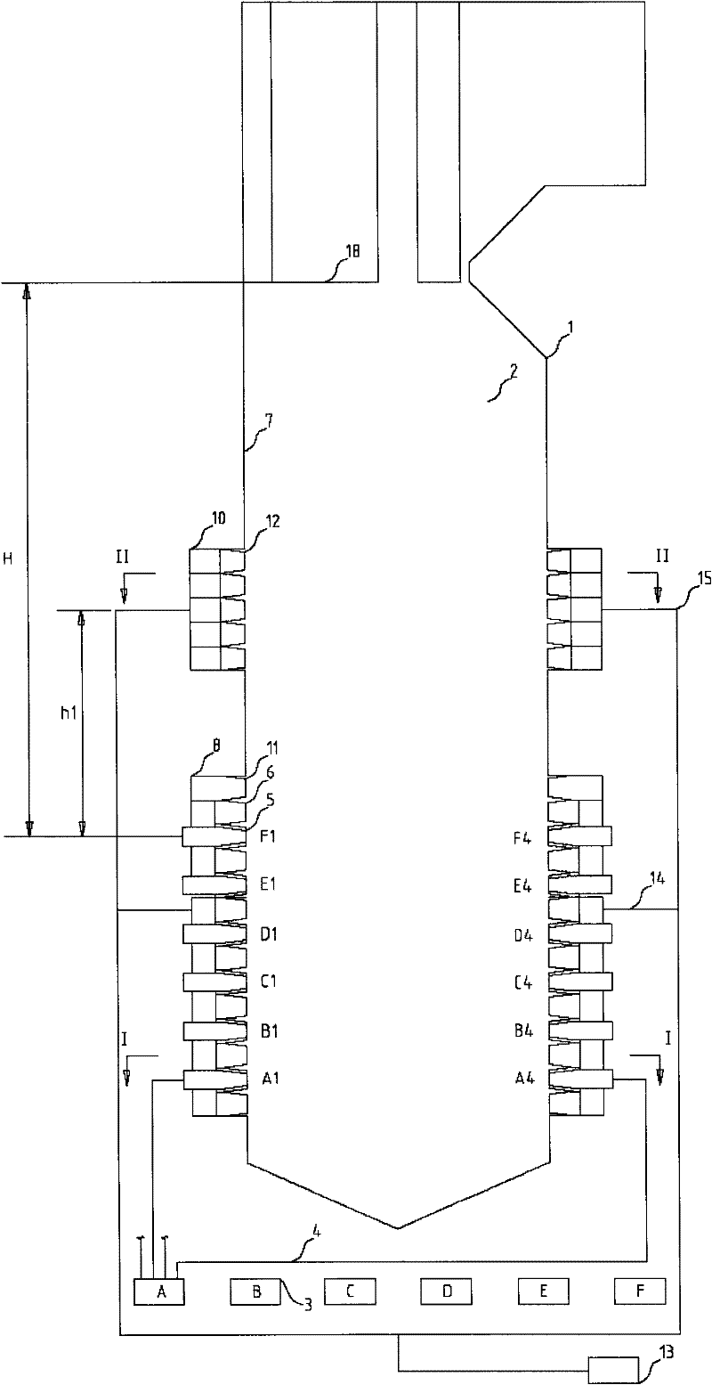
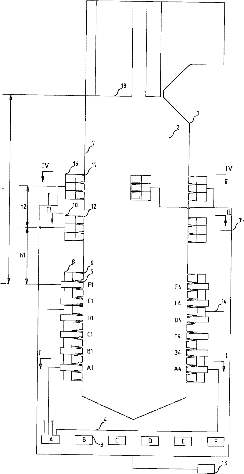
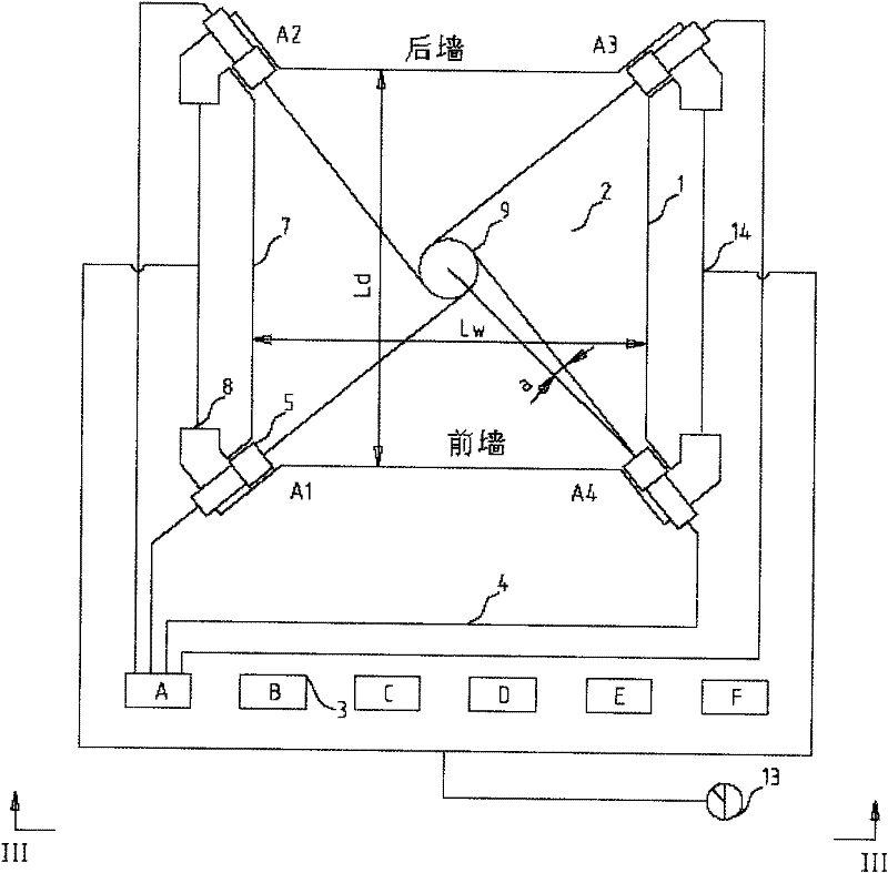
[0039] combine figure 2 , image 3 , Figure 4 and Figure 5 To describe this embodiment, image 3 for figure 2 I-I sectional view, Figure 4 for figure 2 II-II sectional view, Figure 5 for figure 2 Sectional view of IV-IV, figure 2 for image 3 , Figure 4 and Figure 5 Sectional view of III-III.

[0040] A multi-stage burn-off air arrangement method provided by the present invention includes a boiler body 1, a furnace 2, a coal mill 3, a pulverized coal pipeline 4, a primary air pulverized coal nozzle 5, a secondary air nozzle 6, a main burner 8, a low-level Separation overburning air wind box 10, high separation overburning air wind box 16 and furnace horizontal outlet panel superheater 18. Each boiler 1 is equipped with six coal mills 3 . The furnace 2 is composed of four water-cooled walls 7, and a group of main burners 8 are arranged on each corner of the furnace 2, and each group of main burners 8 is vertically arranged with six primary air pulverize...

Embodiment 2

[0053] combine Figure 6 and Figure 7 To describe this embodiment, Figure 7 for Figure 6 The V-V sectional view, Figure 6 for Figure 7 Sectional view of III-III.

[0054] The difference between this embodiment and Embodiment 1 is that the rotation direction of the first high-level imaginary tangent circle 20 formed by the center line of the high-level separation burn-off air nozzle 17 arranged on the four walls is the same as that of the imaginary tangent circle 9 of the main burner 8 and The direction of rotation of the low imaginary tangent circle 19 of the low separation burnout air box 10 is opposite, see Figure 7 .

[0055] At the same time, the distance L1 between the center line of the high-level separation burn-off air nozzle 17 arranged on the front and rear walls and the water-cooled wall 7 is at the corner of the nearest furnace 2 is a quarter of the width Lw of the furnace 2, namely: L1 = 1 / 4Lw, see Figure 7 . Similarly, the distance L2 between the ...

Embodiment 3

[0059] Such as Figure 8 As shown, the difference between this embodiment and Embodiment 1 is that the high-level separation overfire air is arranged in a circle with four corners. Other structures and test results are the same as in Example 1.


PUM


Abstract

The invention provides a multi-stage overburning air arrangement method, including primary air pulverized coal nozzles, secondary air nozzles, main burners, low-position separated overburning air bellows, and high-position separated overburning air bellows, each corner of the furnace There is a group of main burners arranged above, and the separated overburned air is divided into low-level separated overfired air and high-level separated overfired air. The low-level separation overfire air boxes are arranged on the four corners of the furnace or on the four walls. The high-level separation overfire air boxes are arranged on the four corners of the furnace or on the four walls. The present invention can realize low emission of NOx on the basis of controlling the NOx effect of 250-650 mg / m3 (when the oxygen concentration of the flue gas is 6%) based on the overall air classification technology in the furnace burning bituminous coal and lean coal, and further reduce the amount of NOx generated by 15%. about. It solves the problems of high fly ash combustibles caused by the overall air classification technology in the furnace, and the large deviation of flue gas velocity and temperature at the furnace outlet. At the same time, it increases the operation adjustment performance for different coal types and load changes.

Description

technical field [0001] The invention relates to a multi-stage overburning air arrangement method, which belongs to the technical field of combustion devices. Background technique [0002] Nitrogen oxides (NOx, including NO, NO 2 , N 2 O) is a class of gases that can cause serious air pollution and is considered to be one of the main sources of air pollution. Nitrogen oxides from the burning of fossil fuels account for a large proportion of all nitrogen oxide emissions worldwide each year. The increasingly stringent environmental regulations require the research and development of advanced combustion technologies to reduce emissions of pollutants such as NOx. At present, the most important feature of my country's energy composition is coal, accounting for more than 70%, which will produce a large amount of nitrogen oxide gas. Therefore, such an energy structure will have a negative impact on economic and efficient growth and the ecological environment. The existing techni...

Claims


Application Information

Patent Timeline
Patent Type & Authority Patents(China)
IPC IPC(8): F23L9/02F23C7/06
Inventor 张建文柳公权刘家宝李江涛
Owner SHANGHAI BOILER WORKS
Why Eureka
Try Eureka