Plaque stabilisation using cryoenergy

a technology of cryoenergy and plate, applied in the field of plate stabilisation using cryoenergy, can solve the problems of undesirable and potentially dangerous blockage, subsequent stenosis, and danger of use, and achieve the effects of reducing the risk of thrombosis, and reducing the risk of cryotherapy

Active Publication Date: 2015-03-03
CRYOTHERAPEUTICS GMBH
View PDF30 Cites 0 Cited by
  • Summary
  • Abstract
  • Description
  • Claims
  • Application Information

AI Technical Summary

Benefits of technology

[0013]The present invention delivers cryoenergy to a vulnerable plaque that has ruptured, or is likely to rupture, at the surface of a blood vessel in order to modify the plaque structure, i.e. the plaque morphology will change from an unstable to a more stable state, such that healing is aided and the associated risk of thrombus formation is minimised or eliminated.
[0038]According to a further aspect, there may be provided a cryomedical refrigerant system using a liquid refrigerant where the liquid is infused with gaseous bubbles in suspension and where the bubbles expand and burst within the heat transfer section to create a Joule Thomson effect cooling within the liquid refrigerant.

Problems solved by technology

Pressures used in conventional cryocatheters to treat stenotic vessels are typically higher than 5 ATM (507 kPa) such that they may be dangerous to use.
The application of high pressure cryo-energy to an unstable plaque may induce a cellular hyperplasia reaction that leads to subsequent stenosis and, in the short term, an undesirable and potentially dangerous blockage.

Method used


Image

  • Plaque stabilisation using cryoenergy
  • Plaque stabilisation using cryoenergy
  • Plaque stabilisation using cryoenergy

Examples


Embodiment Construction

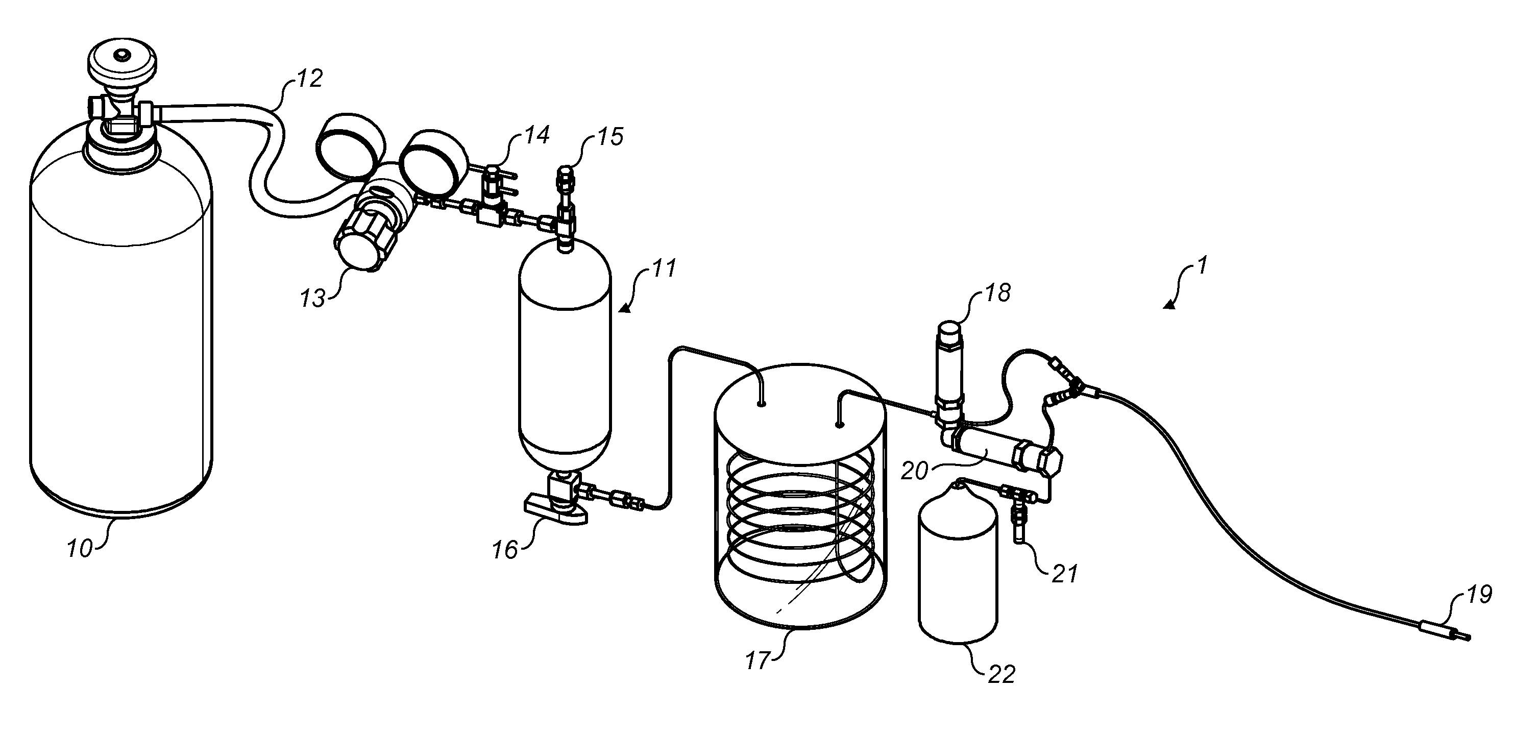
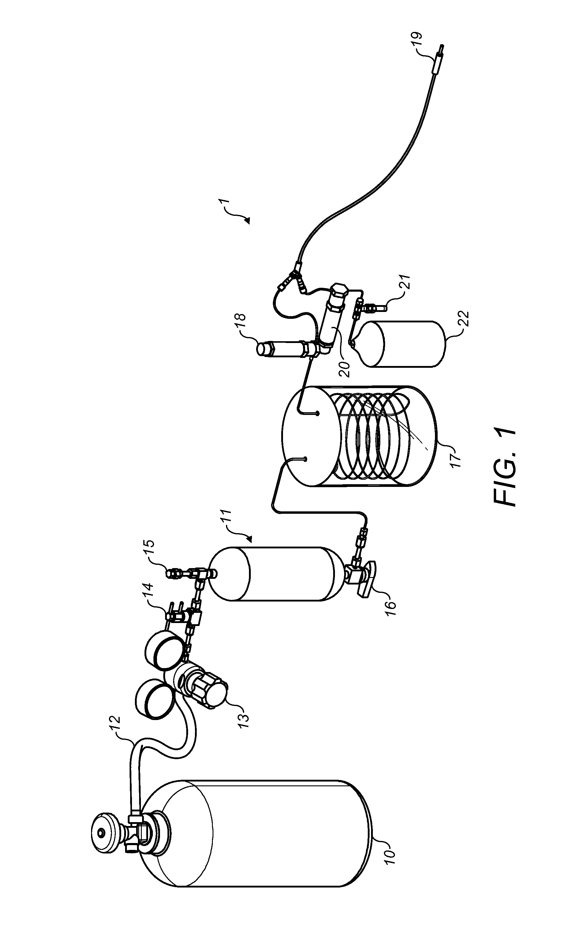
[0050]FIG. 1 is an illustration of an exemplary system for supplying cryoenergy to a target part of a vessel. It will be understood that some of the described components are not essential to the operation of the system but are described for context only. Suitable, functionally similar, or equivalent components may be used interchangeably. It is noted that throughout the present description, all pressures given as gauge pressures, that is, above atmospheric pressure.

[0051]The system 1 includes a pressure source 10, which provides pressure to the system, a fluid reservoir 11 which stores refrigerant, a heat exchanger 17 for cooling the pressurised refrigerant and a catheter 19 which is inserted into a vessel to supply cryoenergy to a target. Alternative methods of supplying cryoenergy to a vessel, without the use of a refrigerant, are contemplated and described with references to FIGS. 6a, 6b and 7 below. These include activating an endothermic reaction and controlling a thermoelectri...


PUM


Abstract

There is provided a method of supplying cryoenergy to a plaque within a blood vessel. The method comprises expanding an expandable membrane of a catheter apparatus with a pressure of less than 5 ATM (507 kPa), the catheter apparatus having been placed in thermal contact with the plaque within the blood vessel. The method also comprises establishing a temperature of between +15° C. (288K) and −35° C. (238K) at an interface of the expandable membrane and the blood vessel. A system and catheter apparatus are also provided.

Description

BACKGROUND OF THE INVENTION[0001]From the late 1970s, cryoenergy has been used in the cardiovascular system starting from, for example, 1977 when it was used to surgically treat cardiac arrhythmias. Over the ensuing years it became widely recognised that cryoenergy was the energy source of choice when working in the heart. Its safety and efficacy was unsurpassed as surgeons were able to ablate delicate cardiac structures such as the A-V node, pulmonary veins and delicate peri-nodal atrial tissue without concern for thrombosis, perforation or other adverse events.[0002]More recently, researchers have started investigating the use of cryoenergy in the vascular system as a method to treat calcified plaque. Clinical data published by Laird et. al. “Cryoplasty for the Treatment of Femoropopliteal Arterial Disease: Extended Follow-up Results” J ENDOVASC THE 2006; 13 (Suppl II): II-52-II-59 has shown that cryoenergy achieves good clinical results when used in highly stenosed vessels of the...

Claims


Application Information

Patent Timeline
Patent Type & Authority Patents(United States)
IPC IPC(8): A61B18/18A61B18/00A61B18/02A61F7/12
CPCA61B18/02A61F7/123A61B2018/00791A61B2018/0212A61B2018/0237A61B2018/0262A61F2007/126A61B18/18A61F7/12A61M25/01A61B2018/0022A61B2018/00345A61B2018/0041
Inventor BUCHBINDER, MAURICEWERNETH, RANDELL LOUISYIANNI, YIANNAKIS PETROUNAHON, DANIELFLAHERTY, J. CHRISTOPHERSANTOIANNI, DOMENIC
Owner CRYOTHERAPEUTICS GMBH
Why Eureka
Try Eureka