Surgical instrument with stamped double-flag jaws and actuation mechanism

a surgical instrument and double-flag technology, applied in the field of surgical instruments, can solve the problems of short circuit, tissue may have a tendency to move before an adequate seal, and prevent energy from being transferred through the tissue,

Active Publication Date: 2015-03-03
TYCO HEALTHCARE GRP LP
View PDF181 Cites 113 Cited by
  • Summary
  • Abstract
  • Description
  • Claims
  • Application Information

AI Technical Summary

Benefits of technology

[0009]The drive rod may extend through the jaw members on a laterally interior side of each of the flanges, and the drive rod may exhibit a generally u-shaped profile. The surgical instrument may further include a knife selectively movable in a longitudinal direction with respect to the drive rod, and the knife may be supported within the u-shaped profile such that the drive rod provides restricts lateral movement of the knife in a first lateral plane. The drive rod may also include an overfold disposed opposite a u-shaped connector portion of the drive rod such that the knife is substantially surrounded on four lateral sides, and such that the overfold and the u-shaped connector portion restrict movement of the knife in a second lateral plane that is orthogonal to the first lateral plane.

Problems solved by technology

If an adequate gap distance is not maintained, there is a possibility that the opposed electrodes will contact one another, which may cause a short circuit and prevent energy from being transferred through the tissue.
Also, if too low a force is applied the tissue may have a tendency to move before an adequate seal can be generated.
Below this range, the seal may shred or tear and above this range the vessel walls may not be effectively joined.

Method used


Image

  • Surgical instrument with stamped double-flag jaws and actuation mechanism
  • Surgical instrument with stamped double-flag jaws and actuation mechanism
  • Surgical instrument with stamped double-flag jaws and actuation mechanism

Examples


Embodiment Construction

[0047]The present disclosure relates to an electrosurgical apparatus and methods for performing electrosurgical procedures. More particularly, the present disclosure relates to electrosurgically sealing tissue. As is traditional, the term “distal” refers herein to an end of the apparatus that is farther from an operator, and the term “proximal” refers herein to the end of the forceps 10 which is closer to the operator.

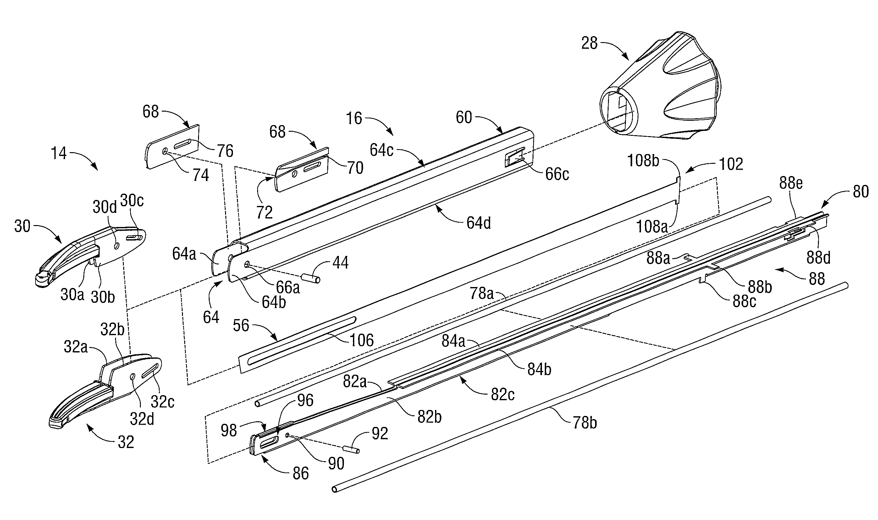
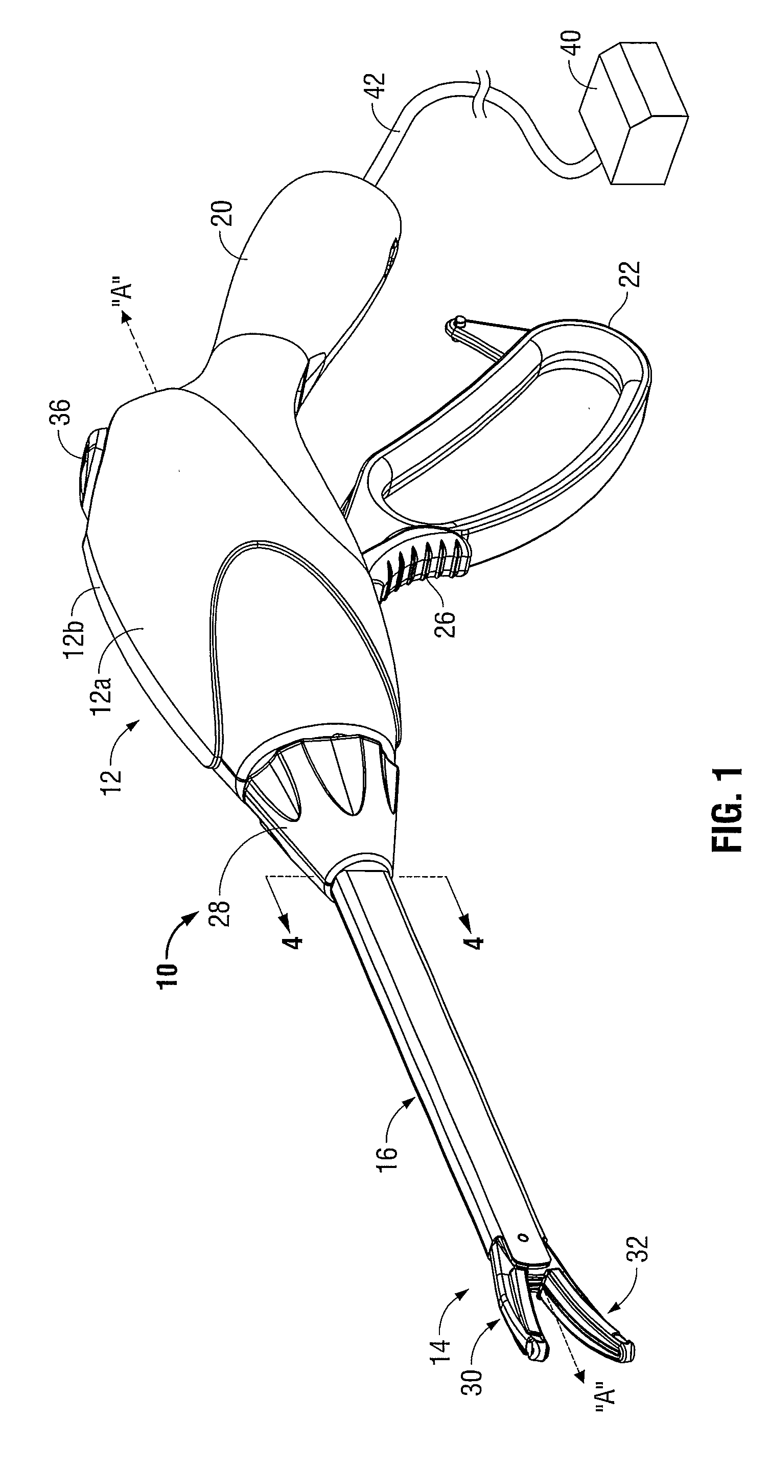
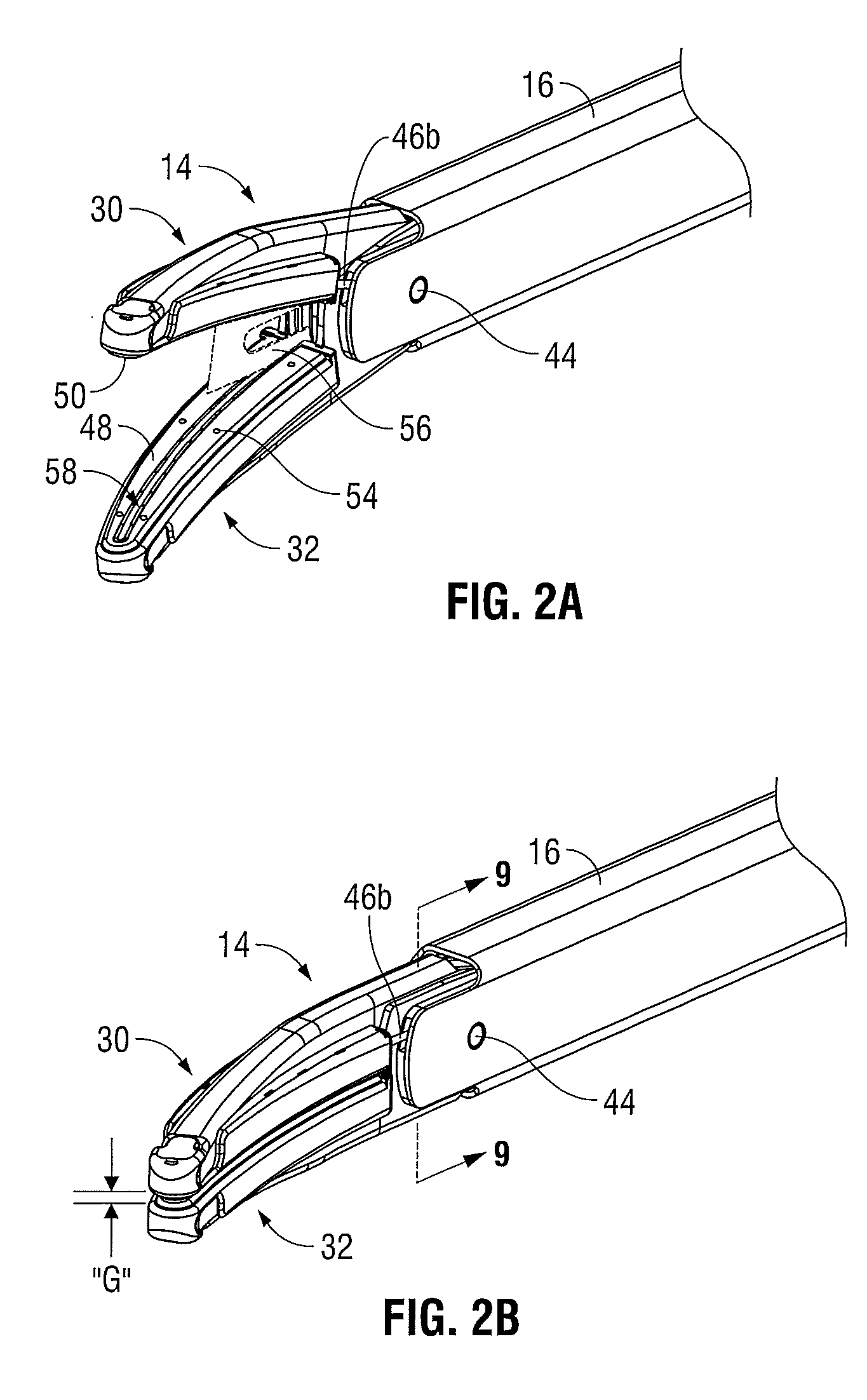
[0048]Referring initially to FIG. 1, an embodiment of an electrosurgical forceps 10 generally includes a housing 12 that supports various actuators thereon for remotely controlling an end effector 14 through an elongated shaft 16. Although this configuration is typically associated with instruments for use in laparoscopic or endoscopic surgical procedures, various aspects of the present disclosure may be practiced with traditional open instruments and in connection with endoluminal procedures as well.

[0049]The housing 12 is constructed of a left housing half 12a and a ...


PUM


Abstract

A surgical instrument includes a housing that supports an elongated shaft. A selectively movable drive rod extends through the elongated shaft and carries a cam pin in a longitudinal direction. An end effector for surgically treating tissue is supported by the elongated shaft and includes upper and lower jaw members pivotally coupled to one another about a pivot axis. The upper jaw member includes a first pair of laterally spaced flanges, and the lower jaw member includes a second pair of laterally spaced flanges defining a camming slot for engaging the cam pin. The flanges are arranged in an offset configuration where one flange of the upper jaw member is positioned on a laterally exterior side of a corresponding flange of the lower jaw member, and the other flange of the upper jaw member is positioned on a laterally interior side of the other flange of the lower jaw member.

Description

BACKGROUND[0001]1. Technical Field[0002]The present disclosure relates generally to the field of surgical instruments. In particular, the disclosure relates to an endoscopic electrosurgical forceps that is economical to manufacture and is capable of sealing and cutting relatively large tissue structures.[0003]2. Background of Related Art[0004]Instruments such as electrosurgical forceps are commonly used in open and endoscopic surgical procedures to coagulate, cauterize and seal tissue. Such forceps typically include a pair of jaws that can be controlled by a surgeon to grasp targeted tissue, such as, e.g., a blood vessel. The jaws may be approximated to apply a mechanical clamping force to the tissue, and are associated with at least one electrode to permit the delivery of electrosurgical energy to the tissue. The combination of the mechanical clamping force and the electrosurgical energy has been demonstrated to join adjacent layers of tissue captured between the jaws. When the adj...

Claims


Application Information

Patent Timeline
Patent Type & Authority Patents(United States)
IPC IPC(8): A61B18/14
CPCA61B18/1445A61B2018/1455A61B18/12A61B18/1442A61B2018/00601A61B2018/1452A61B2018/00982A61B2017/2936F04C2270/0421A61B17/29A61B2017/00367A61B2018/00607A61B2018/0063
Inventor ALLEN, IV, JAMES D.CHOJIN, EDWARD M.BUCCIAGLIA, JOSEPH D.
Owner TYCO HEALTHCARE GRP LP
Why Eureka
Try Eureka