
Method for cleaning hydraulic liquid, computerprogram product, control unit, and industrial truck

a technology of hydraulic liquid and computer program, which is applied in the direction of positive displacement liquid engines, piston pumps, multi-stage water/sewage treatment, etc., can solve the problems of increasing the cost of the hydraulic circuit and confining spacing problems, and achieve the effect of convenient service or exchang

Active Publication Date: 2015-03-03
BT PROD
View PDF7 Cites 1 Cited by
  • Summary
  • Abstract
  • Description
  • Claims
  • Application Information

AI Technical Summary

Benefits of technology

[0016]The effect of this method is thereby that a better cleaning of the hydraulic liquid can occur, through filtration in the return filter, in addition to the filtration that occurs at normal usage of the hydraulic system in the industrial truck.
[0040]The invention also comprises a computer program product comprising machine readable code which when executed in an industrial truck control unit makes the industrial truck perform the method according to the above. The invention further comprises a control unit that comprises the computer program product. The control unit can according to an embodiment constitute an own unit outside a central truck computer. This has the effect that the control unit can in easily be serviced or exchanged. Different control units can easily be adapted depending on how the industrial truck is used, and adaptations can be made also of the control unit's hardware in a convenient way. The control unit can according to an embodiment be integrated in a central truck computer. This has the effect that no additional electronics need to be installed on the industrial truck.

Problems solved by technology

These filters provide problems with pressure losses from the pump, and result in increased costs for the hydraulic circuit.
To introduce a high pressure filter on the pressure side after the pump also confers spacing problems.

Method used


Image

  • Method for cleaning hydraulic liquid, computerprogram product, control unit, and industrial truck
  • Method for cleaning hydraulic liquid, computerprogram product, control unit, and industrial truck
  • Method for cleaning hydraulic liquid, computerprogram product, control unit, and industrial truck

Examples


Embodiment Construction

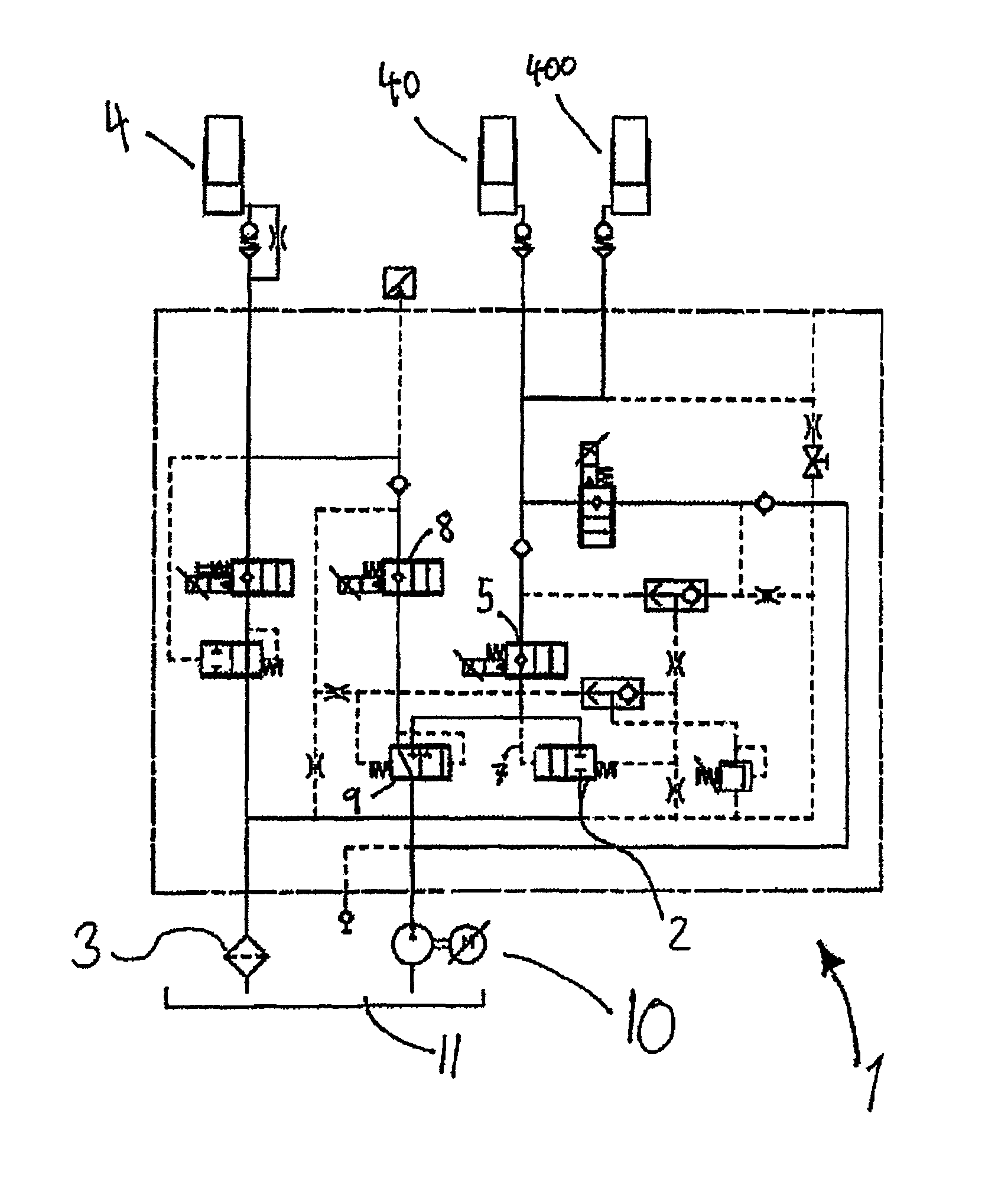
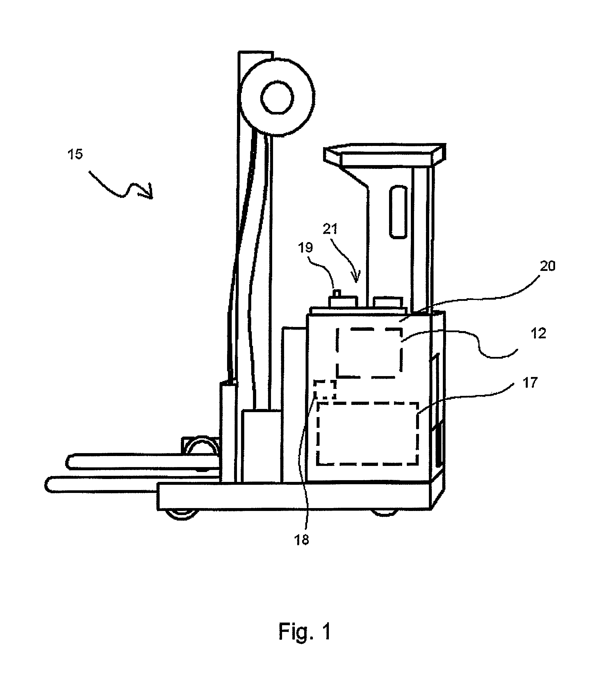
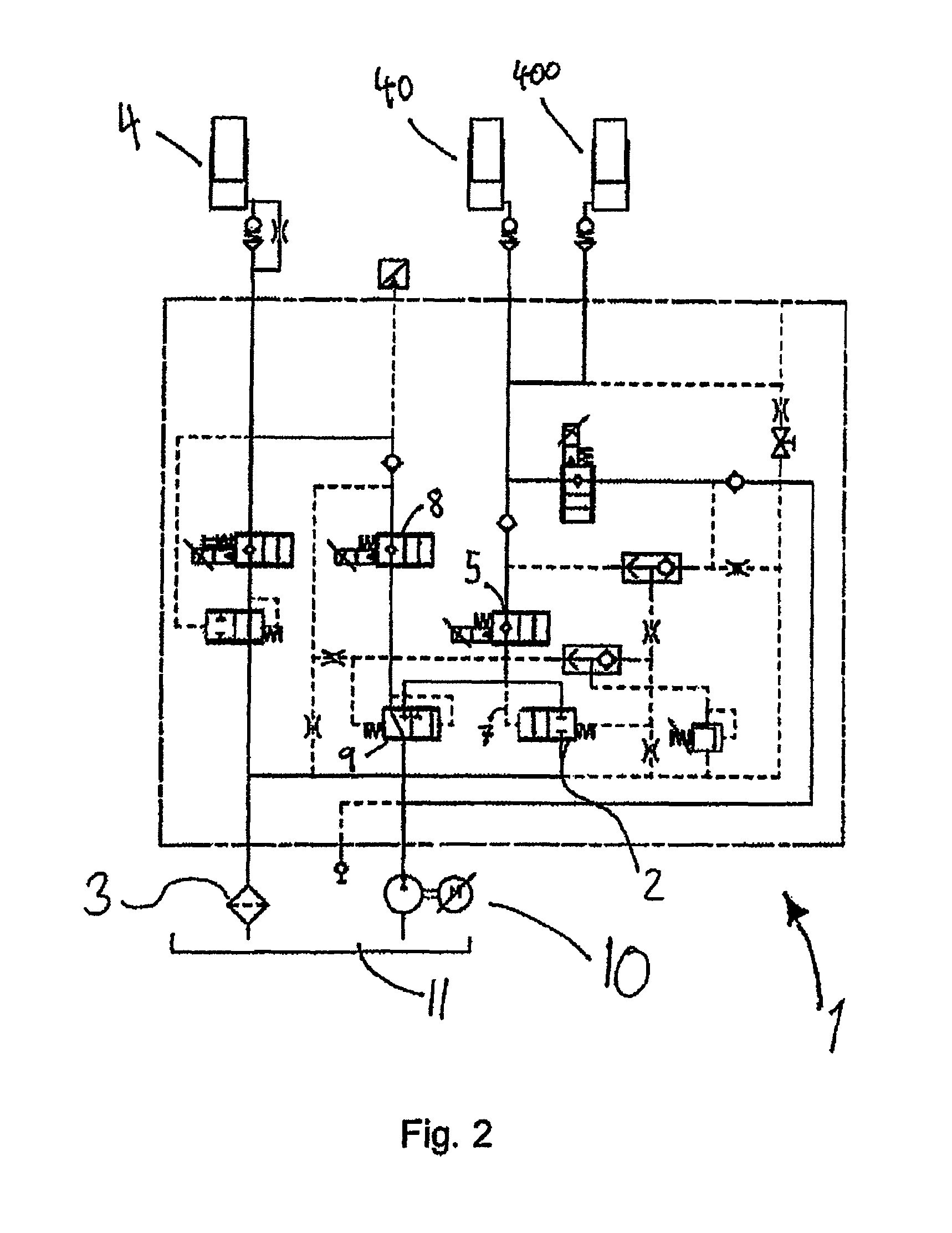
[0052]The invention is now described according to the annexed drawings.

[0053]The method according to the invention consists of performing cleaning of the hydraulic liquid in an industrial truck 15, see FIG. 1. The cleaning is performed by introducing circulation of the hydraulic liquid when hydraulic activity is not present. This occurs by arranging the industrial truck 15 with means for performing this. The industrial truck 15 comprises a hydraulic pump 10, a hydraulic reservoir 11, and a return pipe to the hydraulic reservoir 11. On the return pipe a return filter 3 is positioned. The industrial truck is an electrically powered industrial truck 15 having a battery 17 as an energy source

[0054]The steps of the method is given by the known process for step a and b, where[0055]a. The hydraulic pump 10 is activated for hydraulic activity[0056]b. The hydraulic pump 10 pumps the hydraulic liquid for the hydraulic activity and in relation to this return flow occurs through the return filt...


PUM

PropertyMeasurementUnit
purityaaaaaaaaaa
circulation timeaaaaaaaaaa
areaaaaaaaaaaa

Abstract

Method for cleaning hydraulic liquid in a industrial truck, wherein said industrial truck is an electrically powered industrial truck having a battery as an energy source with a hydraulic system comprising, a hydraulic pump, a hydraulic reservoir, and a return pipe to the hydraulic reservoir with a return filter, wherein the method comprises the steps of, the hydraulic pump is activated for hydraulic activity, the hydraulic pump pumps the liquid for the hydraulic activity and in relation to this return flow through the return filter to the hydraulic reservoir occurs, the hydraulic pump can be activated by means comprised in the industrial truck, when hydraulic activity is not present, by that achieving a circulation to the hydraulic reservoir through the return filter such that sufficient filtration of the hydraulic liquid is reached, further a time Tb for circulation without hydraulic activity can be accumulated and / or a sensor for determining the quality of the hydraulic oil can be arranged in the industrial truck. Termination of the circulation is based on Tb and / or the measured quality. The application also relates to a computer program product, a control unit and an industrial truck that can perform the method.

Description

TECHNICAL AREA[0001]The present invention relates to the area of industrial trucks. More specifically to the hydraulic system in industrial trucks cleaning of hydraulic liquid.[0002]In particular the present invention relates to electrically driven industrial trucks, using a battery as a power source.BACKGROUND[0003]It is previously known to clean hydraulic liquid in industrial trucks.[0004]Hydraulic systems in general, have an incorporated filter which is positioned at the return flow to a container for the hydraulic liquid, generally named the hydraulic reservoir. This filter is of low pressure type. The filter cleans the liquid by means of the return flow to the hydraulic reservoir. In JP 6081815 A, such a hydraulic circuit is disclosed, in which the idea of cleaning with a low pressure filter at the hydraulic reservoir has been further developed. JP 6081815 A discloses a hydraulic circuit with a pump, two hydraulic pistons, the hydraulic circuit presents further two direction ch...

Claims


Application Information

Patent Timeline
Patent Type & Authority Patents(United States)
IPC IPC(8): C02F1/00F04B9/08B62D5/00B66F9/22F15B21/041
CPCB66F9/22F15B21/041B66F9/075
Inventor BARNSTROM, JOAKIM
Owner BT PROD
Learn More