Optical system and optical apparatus having the same

a technology applied in the field of optical system and optical apparatus, can solve the problems of difficult to maintain long back focus, and difficult correction, and achieve the effect of high optical performan

Inactive Publication Date: 2015-03-03
CANON KK
View PDF6 Cites 6 Cited by
  • Summary
  • Abstract
  • Description
  • Claims
  • Application Information

AI Technical Summary

Benefits of technology

[0011]The present invention provides an optical system and an optical apparatus which has a high optical performance, and properly corrected aberrations, such as a spherical aberration and a curvature of field.

Problems solved by technology

In an attempt to obtain a wider angle of view with this image pickup optical system, it is difficult to maintain long the back focus.
On the other hand, in an attempt to maintain long the back focus, a variety of aberrations, in particular a curvature of field, accordingly increases and their corrections become difficult.
Thus, similar problems occur in an attempt to obtain a wider angle of view, as described above.
It is difficult for the image pickup optical systems disclosed by Tsuji to realize both a wider angle of view with a shorter overall lens length because the focal length has an approximately inverse relationship with the overall lens length.
In addition, in an attempt to obtain a wider angle of view, it is difficult to maintain long the back focus.
When the correction is made using the swelling spherical aberration curve, it becomes difficult to form a uniform image plane at peripheral angles of field in the screen.
However, as a much wider angle of view is sought, a spherical aberration and a curvature of field increase, and it becomes difficult to obtain a high optical performance over the entire screen.
If this lens structure is improper, it becomes difficult to properly correct the spherical aberration and the curvature of field and to obtain a high optical performance.

Method used


Image

  • Optical system and optical apparatus having the same
  • Optical system and optical apparatus having the same
  • Optical system and optical apparatus having the same

Examples


first embodiment

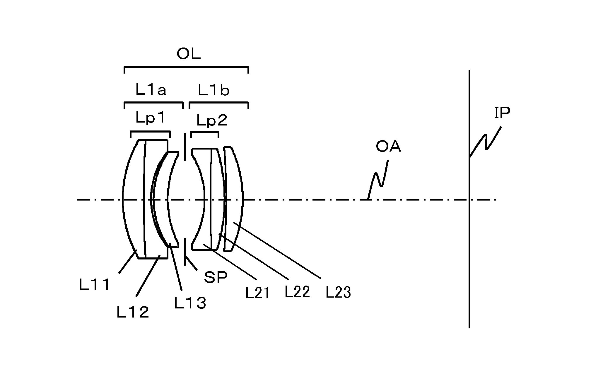
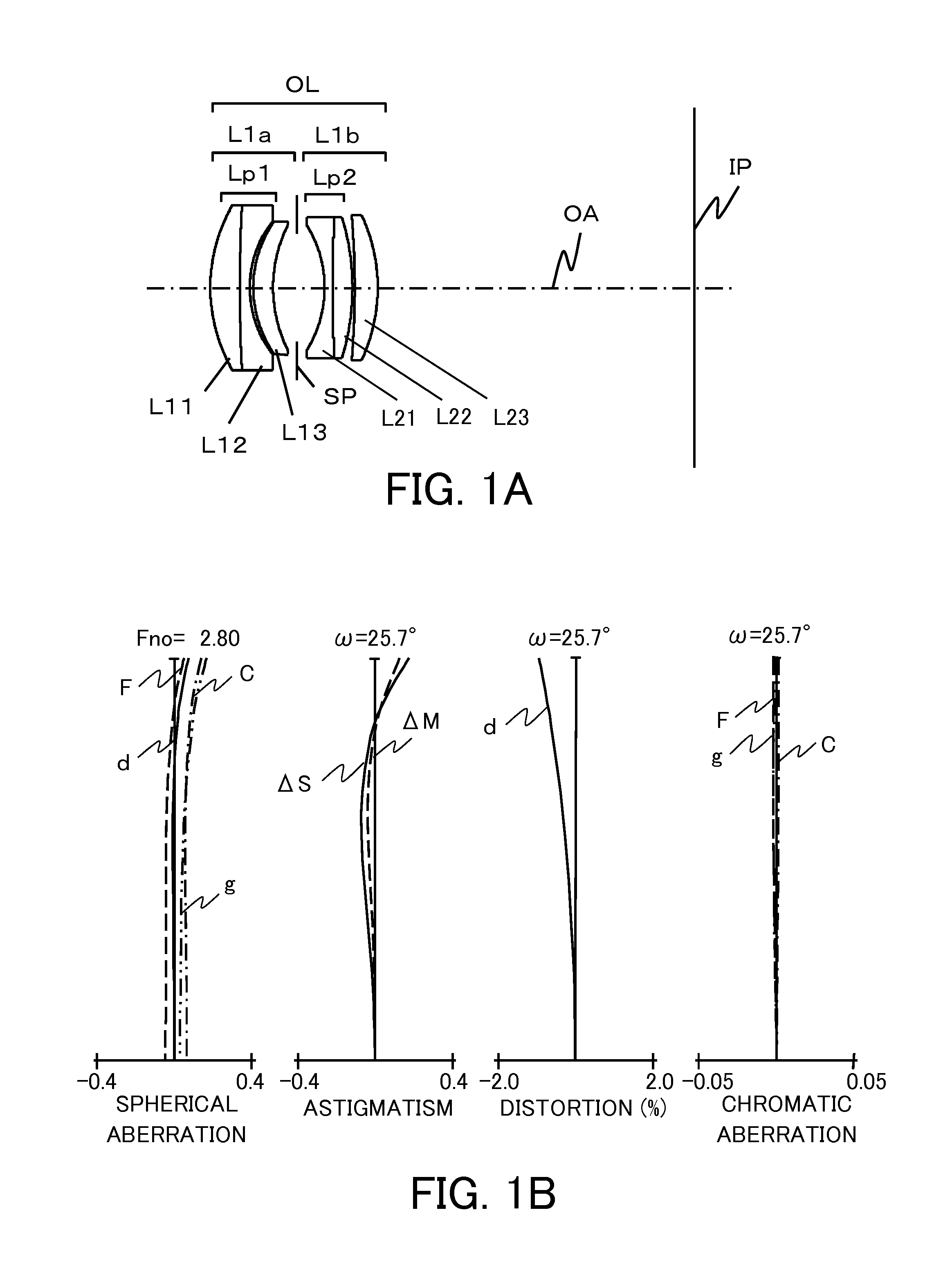
[0057]A description will be given of the optical system OL according to the first embodiment illustrated in FIGS. 1A and 1B. The following values relating to the lengths mean the following numerical examples expressed in millimeters. The optical system OL according to the first embodiment has a focal length of 45.0 mm, and an image pickup angle of view 2ω of 51.4° (therefore half an angle of view ω is 25.7°). The optical system OL illustrated in FIG. 1A includes, in order from the object side to the image side, a first lens unit L1a of a positive refractive power having a synthetic focal length of 101.3 mm, an aperture diaphragm SP, and a second lens unit L1b of a positive refractive power having a synthetic focal length of 54.4 mm.

[0058]The first lens unit L1a includes, in order from the object side to the image side, a cemented lens Lp1 having a synthetic focal length of −300.0 mm made by joining the positive first lens (of a positive refractive power) L11 and the negative second ...

second embodiment

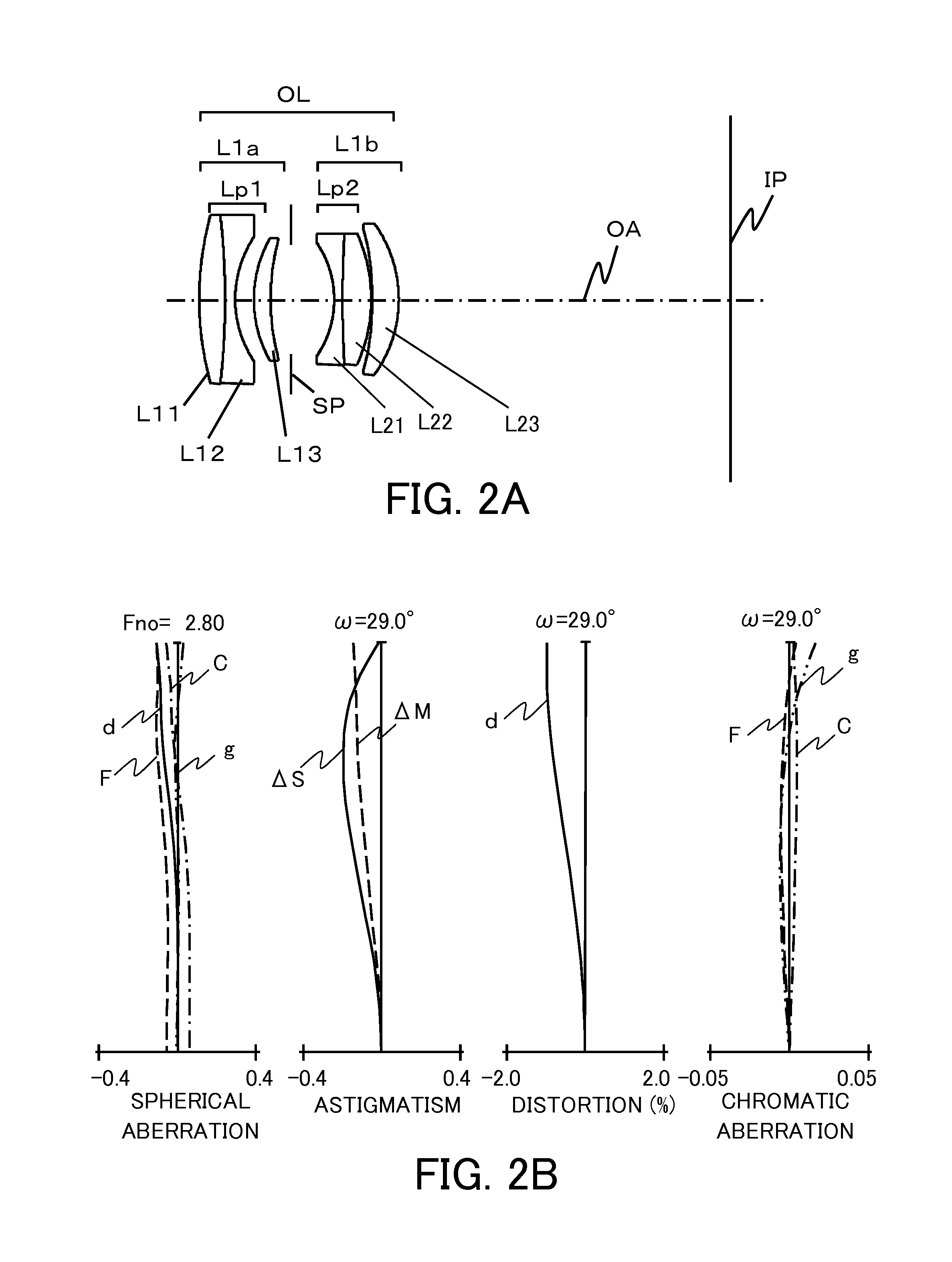
[0062]A description will be given of the optical system OL according to the second embodiment illustrated in FIGS. 2A and 2B. The optical system OL according to the second embodiment has a focal length of 39.0 mm, and an image pickup angle of view 2ω of 58.0° (therefore half an angle of view ω is 29.0°). The optical system OL illustrated in FIG. 2A includes, in order from the object side to the image side, a first lens unit L1a of a positive refractive power having a synthetic focal length of 117.5 mm, an aperture diaphragm SP, and a second lens unit L1b of a positive refractive power having a synthetic focal length of 45.5 mm.

[0063]The first lens unit L1 a includes, in order from the object side to the image side, a cemented lens Lp1 having a synthetic focal length of −76.5 mm made by joining the positive first lens L11 and the negative second lens L12 with each other, and the positive third lens L13 having a meniscus shape.

[0064]The second lens unit L1b includes, in order from the...

third embodiment

[0068]A description will be given of the optical system OL according to the third embodiment illustrated in FIGS. 3A and 3B. The optical system OL according to the third embodiment has a focal length of 35.0 mm, and an image pickup angle of view 2ω of 63.4° (therefore half an angle of view ω is 31.7°). The optical system OL illustrated in FIG. 3A includes, in order from the object side to the image side, a first lens unit L1a of a positive refractive power having a synthetic focal length of 130.3 mm, an aperture diaphragm SP, and a second lens unit L1b of a positive refractive power having a synthetic focal length of 38.1 mm.

[0069]The first lens unit L1a includes, in order from the object side to the image side, a cemented lens Lp1 having a synthetic focal length of −32.6 mm made by joining the positive first lens L11 and the negative second lens L12 with each other, and the positive third lens L13 having a meniscus shape. The second lens unit L1b includes, in order from the object ...


PUM


Abstract

An optical system includes, in order from an object side to an image side, a first lens unit of a positive refractive power, an aperture diaphragm, and a second lens unit of a positive refractive power. The first lens unit includes, in order from the object side to the image side, a cemented lens Lp1 made by joining a first lens of a positive refractive power and a second lens of a negative refractive power with each other, and a third lens of a positive refractive power which has a meniscus shape. The predetermined conditions are satisfied.

Description

BACKGROUND OF THE INVENTION[0001]1. Field of the Invention[0002]The present invention relates to an optical system and an optical apparatus having the same. The present invention is suitable, for example, for a digital still camera, a digital video camera, a surveillance camera, a film-based camera, and a projector.[0003]2. Description of the Related Art[0004]As an image pickup optical system for use with an optical apparatus, such as a digital camera and a video camera, there are known a variety of optical systems each having a back focus equal to or longer than a focal length. For example, a wide variety of image pickup optical systems are known such as a double gauss type, a retro focus type, an ortho-meta type, a plasmat type, and a hexanon type.[0005]Sadahiko Tsuji, “All about Lens Design” Dempa Newspaper Corporation, 2006, pp. 271, 288, and 230 (referred to as “Tsuji” hereinafter) discloses an image pickup optical system having a focal length from 28 mm to 50 mm (and half an i...

Claims


Application Information

Patent Timeline
Patent Type & Authority Patents(United States)
IPC IPC(8): G02B15/15G02B9/34G02B15/14G02B15/173H04N5/225
CPCG02B15/14H04N5/225G02B15/173G02B9/34G02B15/1421H04N23/00
Inventor MAETAKI, SATOSHI
Owner CANON KK
Why Eureka
Try Eureka