Sectional construction assemblies

a technology of sectional construction and assembly, which is applied in the direction of walls, parkings, special buildings, etc., can solve the problems of large system drawbacks, difficult the inability to meet the needs of large structural support of glass panels,

Active Publication Date: 2015-03-10
SAFFORD FRANZ
View PDF44 Cites 13 Cited by
  • Summary
  • Abstract
  • Description
  • Claims
  • Application Information

AI Technical Summary

Problems solved by technology

In these systems, panes of glass are attached to, and supported by, an aluminum framework; however, such systems suffer from substantial drawbacks.
One problem presented by conventional glass wall systems is the need for significant structure to support the panes of glass.
Implementing such an extensive framework is often costly due, at least in part, to the amount of construction material required and the time needed to build the framework.
Additionally, horizontal and vertical supports generally are connected together in a substantially unitary manner, and such restriction often limits architectural design options for an engineer or architect employing such a system.
Another problem involves the difficulty associated with constructing conventional point-support frameworks.
In generally, these holes typically are drilled with a relatively high degree of precision, or the pane of glass may not properly fit within the structure.
Moreover, holes in the glass panels general present additional problems associated with sealing the glass wall from the exterior environment.
Thus, the time and skill required to drill holes in the glass panes and mount the panes on existing framing systems becomes a substantial portion of the overall cost of implementing conventional point-supported glass wall systems.
The amount of structural support typically required in conventional glass wall systems also exacts a toll on the aesthetic properties of the framework system.
While a glass wall with fewer supporting elements may give the appearance of a wall made nearly entirely of glass, the volume of columns, beams and other structural elements typically found in conventional point-supported glass walls often detract from their appearance and overall aesthetic appeal.

Method used


Image

  • Sectional construction assemblies
  • Sectional construction assemblies
  • Sectional construction assemblies

Examples


Embodiment Construction

[0025]The following representative descriptions of the present invention generally relate to exemplary embodiments and the inventor's conception of the best mode, and are not intended to limit the scope, applicability or configuration of the invention in any way. Rather, the following description is intended to provide convenient illustrations for implementing various embodiments of the invention. As will become apparent, changes may be made in the function and / or arrangement of any of the elements described in the disclosed exemplary embodiments without departing from the spirit and scope of the invention.

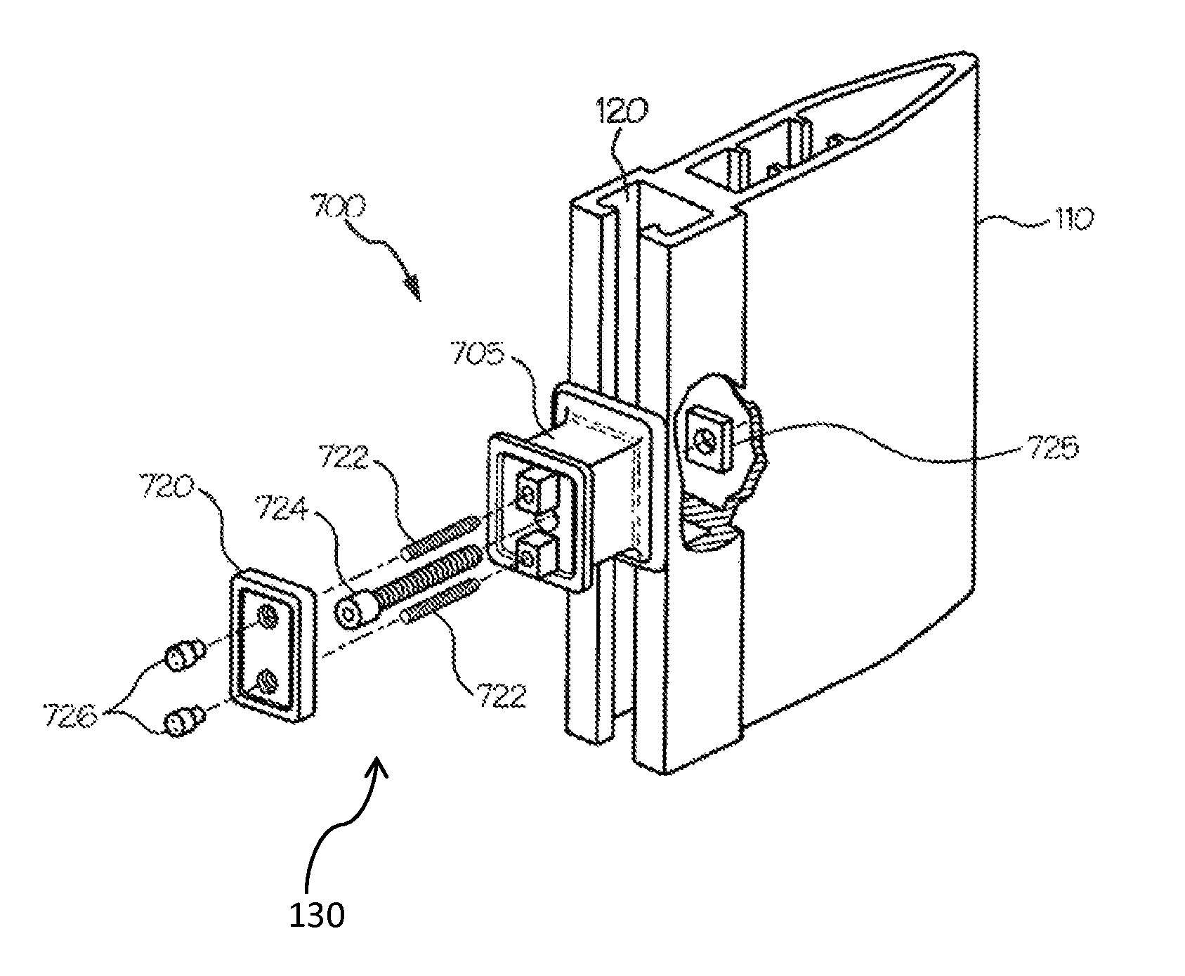
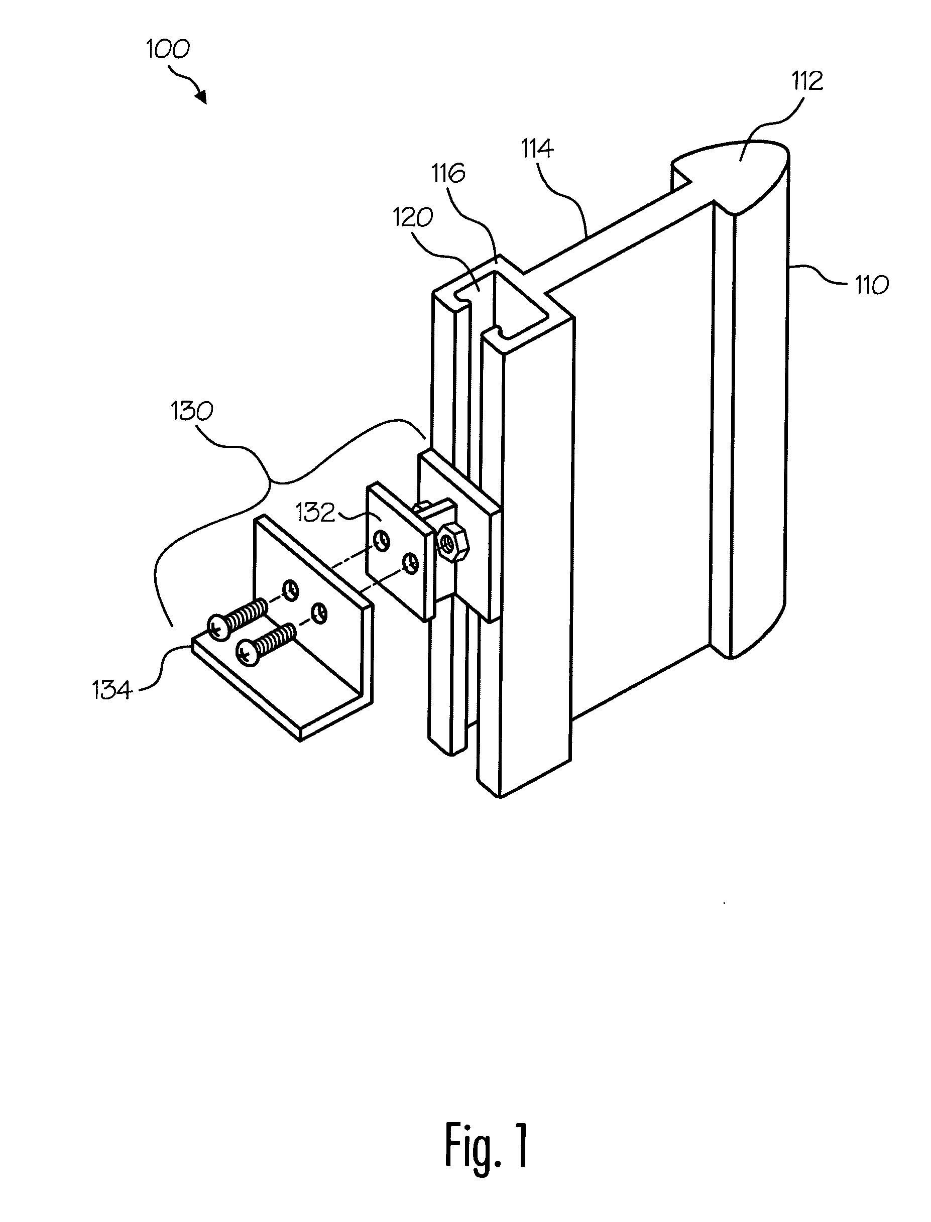
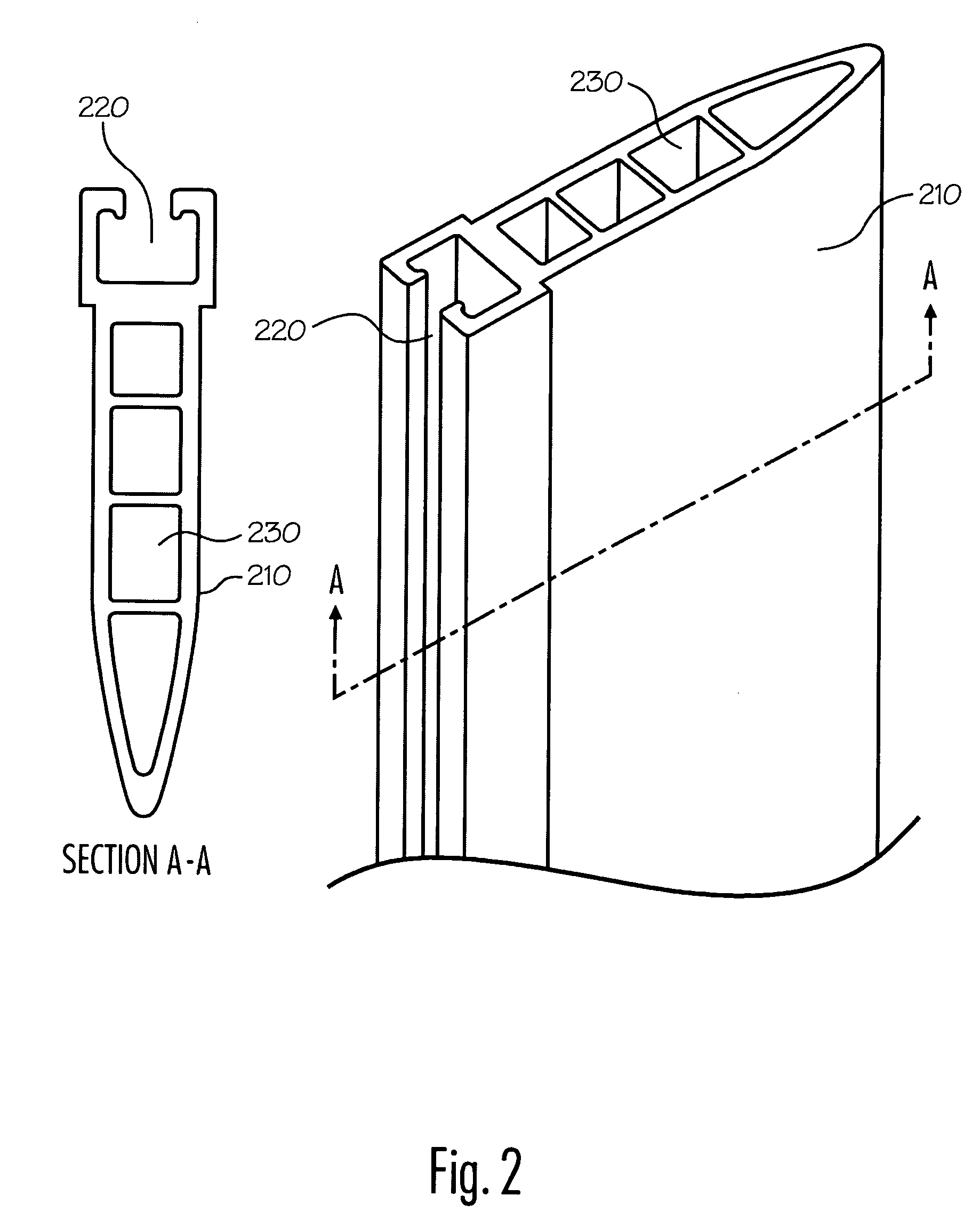
[0026]Various representative implementations of the present invention may be applied to any system for construction. Certain representative implementations may include systems and methods tailored to a specific type of construction, such as point-supported glass wall systems. A detailed description of an exemplary application, namely a construction system for point-supported glass...


PUM


Abstract

The disclosed system, method and device for construction generally includes a mullion having a guide track disposed therein and a custom fitting suitably adapted to support a construction section via substantially adjustable attachment to the guide track. Disclosed features and specifications may be optionally controlled, adapted or otherwise modified to improve the retention and / or support of construction sections in a variety of operating environments. Exemplary embodiments of the present invention generally provide improved aesthetic presentation and mechanical retention of construction panels in point-supported glass wall systems.

Description

RELATED APPLICATIONS[0001]This application claims priority to U.S. Provisional Patent Application Ser. No. 60 / 724,996 filed in the United States Patent and Trademark Office on Oct. 7, 2005 by Franz Safford.FIELD OF INVENTION[0002]The present invention generally concerns systems and methods for assembling construction sections; and more particularly, representative and exemplary embodiments of the present invention generally relate to assembly and construction of glass panel walls.BACKGROUND OF INVENTION[0003]A variety of systems are used in the construction of buildings. Many of these systems employ a framework, such as in the case of conventional point-supported and conventional glass wall systems. In these systems, panes of glass are attached to, and supported by, an aluminum framework; however, such systems suffer from substantial drawbacks.[0004]One problem presented by conventional glass wall systems is the need for significant structure to support the panes of glass. Existing ...

Claims


Application Information

Patent Timeline
Patent Type & Authority Patents(United States)
IPC IPC(8): E04B2/88E04B2/96E06B3/54
CPCE04B2/96E04B2/885E06B3/5427
Inventor SAFFORD, FRANZ
Owner SAFFORD FRANZ
Why Eureka
Try Eureka