Methods and apparatus for batting tee having rapid return

a technology of batting tees and tees, which is applied in the field of methods and apparatus for batting tees having rapid return, can solve the problems of limited durability, tees can damage a bat striking the post, and types of tees also tend to tip

Active Publication Date: 2015-03-17
PROMOUNDS LLC
View PDF44 Cites 14 Cited by
  • Summary
  • Abstract
  • Description
  • Claims
  • Application Information

AI Technical Summary

Benefits of technology

[0005]The tee can further include one or more of the following features: a magnet to secure the post to the base, the first spring comprises a compression spring, a first spring barrier coupled to the cable to contain the first spring in a first cavity and a second spring barrier coupled to the cable to contain the second spring in a second cavity, the first spring barrier comprises a washer, a first clamp secured to the cable proximate the first spring barrier and a second clamp secured to the cable proximate the second spring barrier, the pivot mechanism comprises a connector shaped to increase a distance between the first and second cavities as the post flexes at the pivot point, the connector is shaped to prevent the post from being locked in a flexed position, the connector comprises a groove to prevent the post from being locked in the flexed position, and / or a magnet contained in the post and a ferromagnetic material in the base to removably secure the post to the base.
[0007]The tee can further include one or more of the following features: the first spring comprises a compression spring, a first spring barrier coupled to the cable to contain the first spring in a first cavity and a second spring barrier coupled to the cable to contain the second spring in a second cavity, the pivot mechanism comprises a connector shaped to increase a distance between the first and second cavities as the post flexes at the pivot point, the pivot point mechanism comprises a connector that includes a groove to prevent the post from being locked in the flexed position, and / or a ferromagnetic material in the base to removably secure the post to the base.

Problems solved by technology

Some conventional batting tees include posts of a relatively rigid material that tend to deform, e.g., bend, over time due to contact with a bat, and thus, have limited durability.
In addition, these tees can damage a bat striking the post in the case of a miss hit.
These types of tees also tend to tip over when the bat strikes the post.
However, the post continues to move back and forth for a significant length of time, such as in the order of minutes.
In addition, the spring requires a significant amount of time to return to its quiescent state.

Method used


Image

  • Methods and apparatus for batting tee having rapid return
  • Methods and apparatus for batting tee having rapid return
  • Methods and apparatus for batting tee having rapid return

Examples


Embodiment Construction

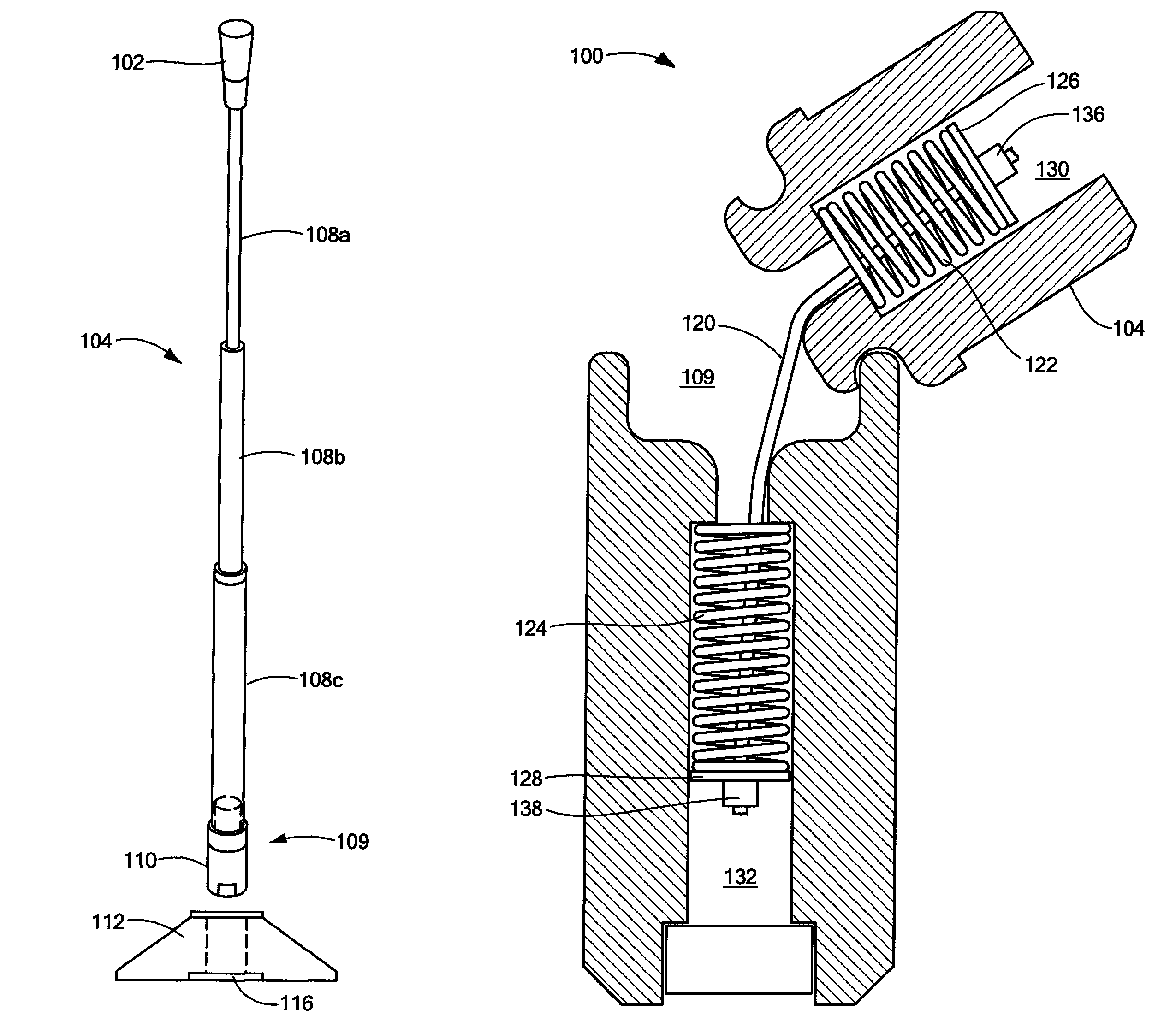
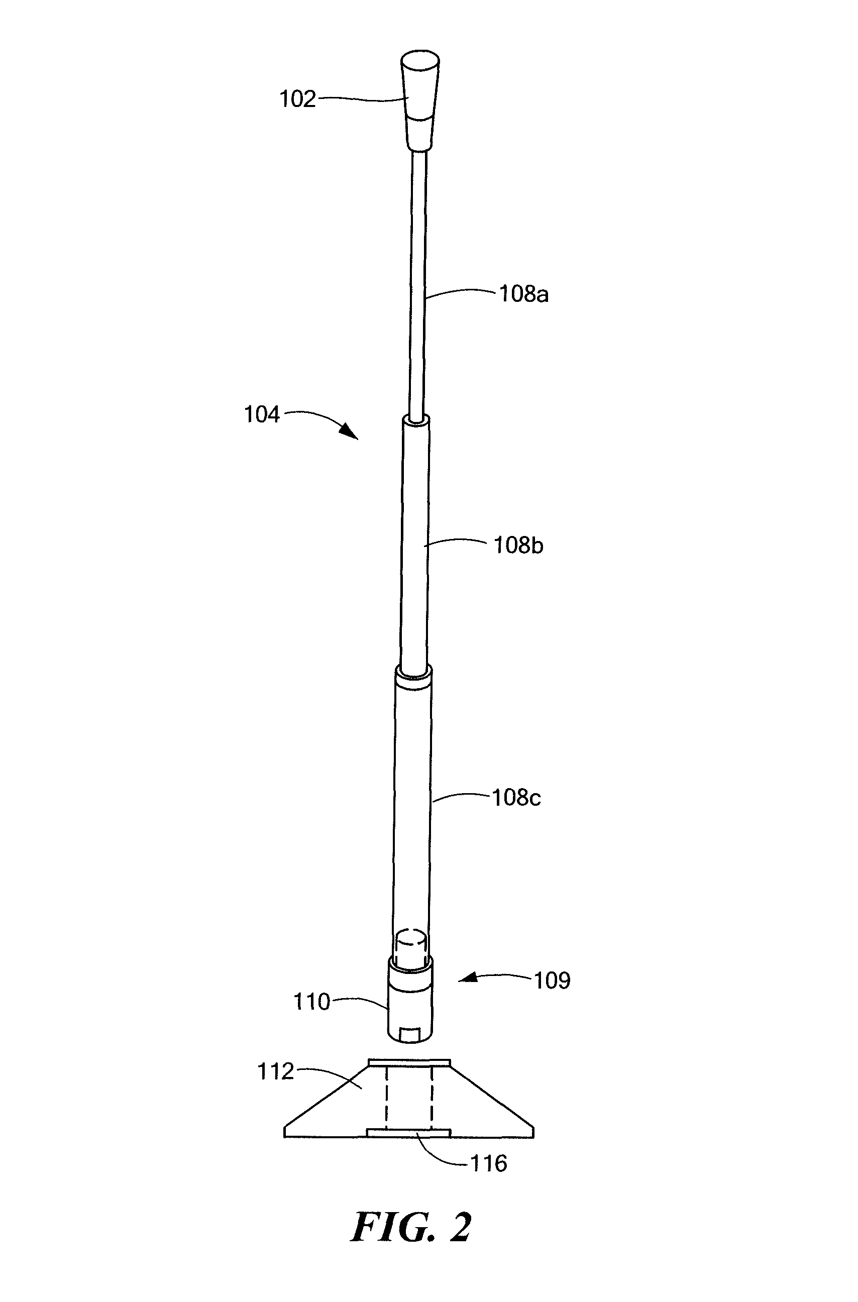
[0018]FIG. 2 shows a batting tee 100 having a ball holder 102 at one end of a telescoping post 104 removably secured to a base 106. In one embodiment, tubing sections 108a, b, c having diameters to provide a telescoping configuration. A first tubing section 108a, fits into a second tubing section 108b, which fits into a third telescoping section 108c.

[0019]A pivot point 109 is located between first and second springs (FIG. 3), as described more fully below. When a batter strikes the ball holder 102 or post 104, the portion of the post about the pivot point 108 moves, such as rotating down to the ground. Upon rotating, or hitting the ground, the post 104 quickly returns, e.g., in the order of a few seconds, to a stable, vertical position. The batter can then place another ball on the holder and continue practicing.

[0020]A bottom of the post 104 includes a post connector 110 for mating with a base connector 112 forming a part of the base 106. In an exemplary embodiment, the post conn...


PUM


Abstract

Methods and apparatus for a batting tee having a base removably matable to a post that includes a pivot mechanism including a pivot point located between axially aligned first and second springs connected to a cable extending along a coincident longitudinal axis of the first and second springs. The pivot point allows the post to rotate at the pivot point in response to an impact on the ball holder and / or post. The springs force the post back to an upright position.

Description

BACKGROUND[0001]As is known in the art, baseball and softball players often use a batting tee to practice hitting a ball. The batter places the ball on the tee and takes a practice swing to strike the ball. Some conventional batting tees include posts of a relatively rigid material that tend to deform, e.g., bend, over time due to contact with a bat, and thus, have limited durability. In addition, these tees can damage a bat striking the post in the case of a miss hit. These types of tees also tend to tip over when the bat strikes the post.[0002]Another known type of tee 10 is shown in FIG. 1. The tee 10 includes a rigid post 12 with a ball holder 14 at one end and a spring 16 at the other end. The spring 16 is secured to a base 18. In the case of a miss hit of the ball, the bat can strike the post 12 causing the spring 16 to flex. However, the post continues to move back and forth for a significant length of time, such as in the order of minutes. The batter must grab the post and s...

Claims


Application Information

Patent Timeline
Patent Type & Authority Patents(United States)
IPC IPC(8): A63B71/00A63B69/00
CPCA63B69/0075A63B69/0002A63B69/00A63B2069/0008A63B2225/093A63B2071/026A63B2209/08A63B2210/50
Inventor MURPHY, JOSEPH T.BESHERE, CHRISTOPHER S.RULLO, JR., WILLIAM E.
Owner PROMOUNDS LLC
Why Eureka
Try Eureka