Arrangement for minimal access surgery

a minimal access and surgery technology, applied in the field of endoscopic minimal access surgery, can solve the problems of damage to the endoscope, delay in surgery, and difficulty for surgeons to maintain the proper location of the endoscop

Active Publication Date: 2013-03-07
STRYKER CORP
View PDF20 Cites 15 Cited by
  • Summary
  • Abstract
  • Description
  • Claims
  • Application Information

AI Technical Summary

Benefits of technology

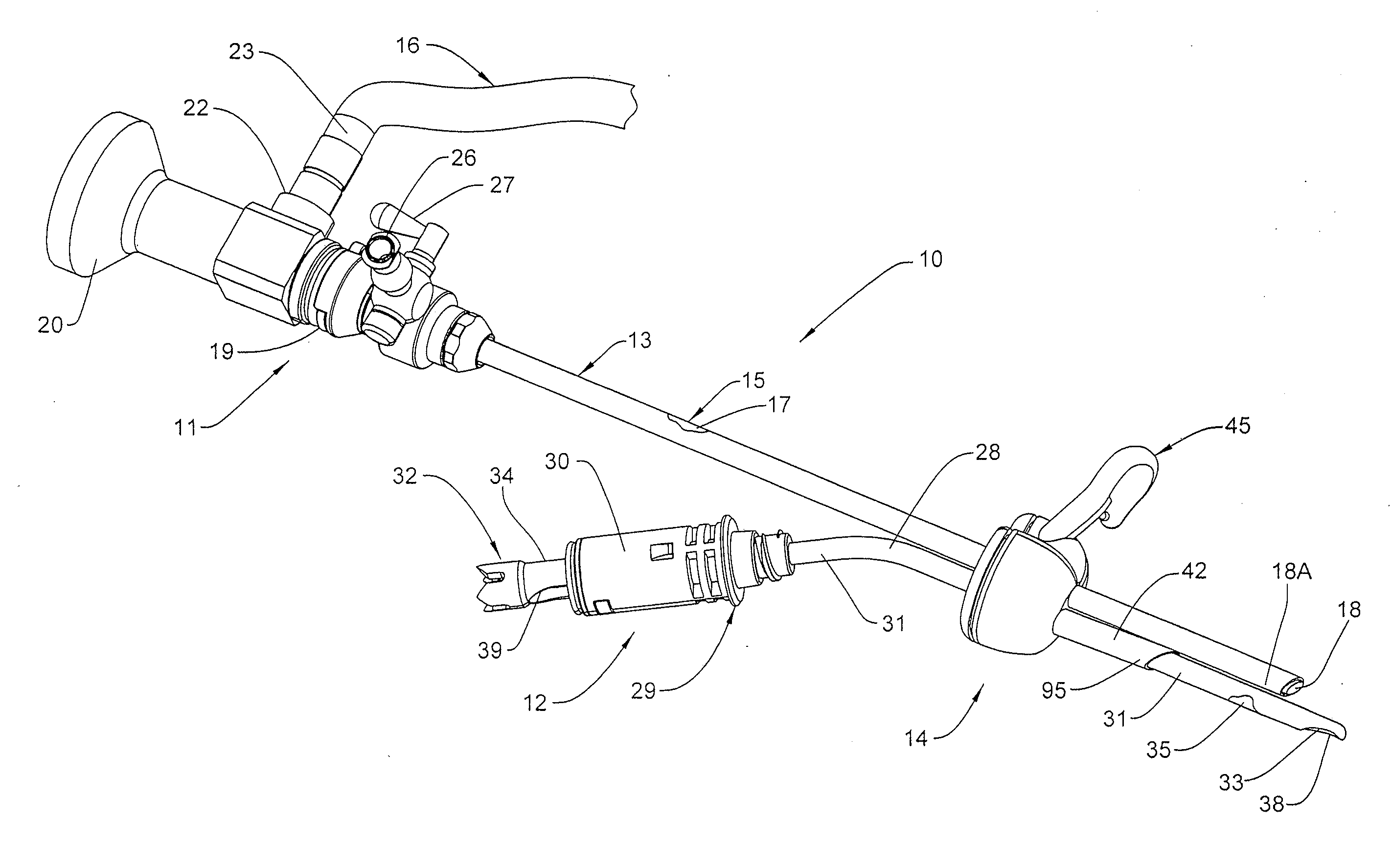
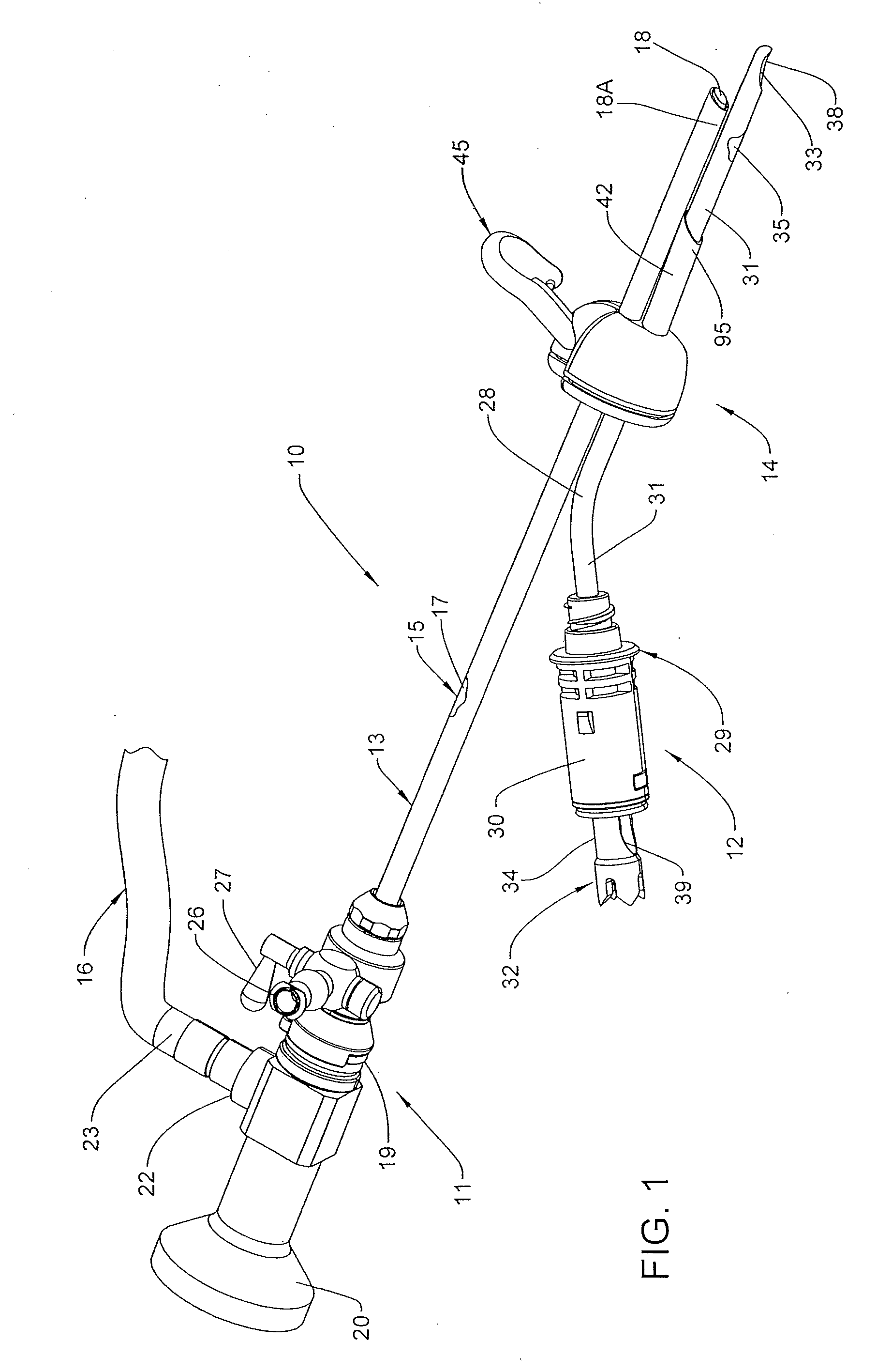
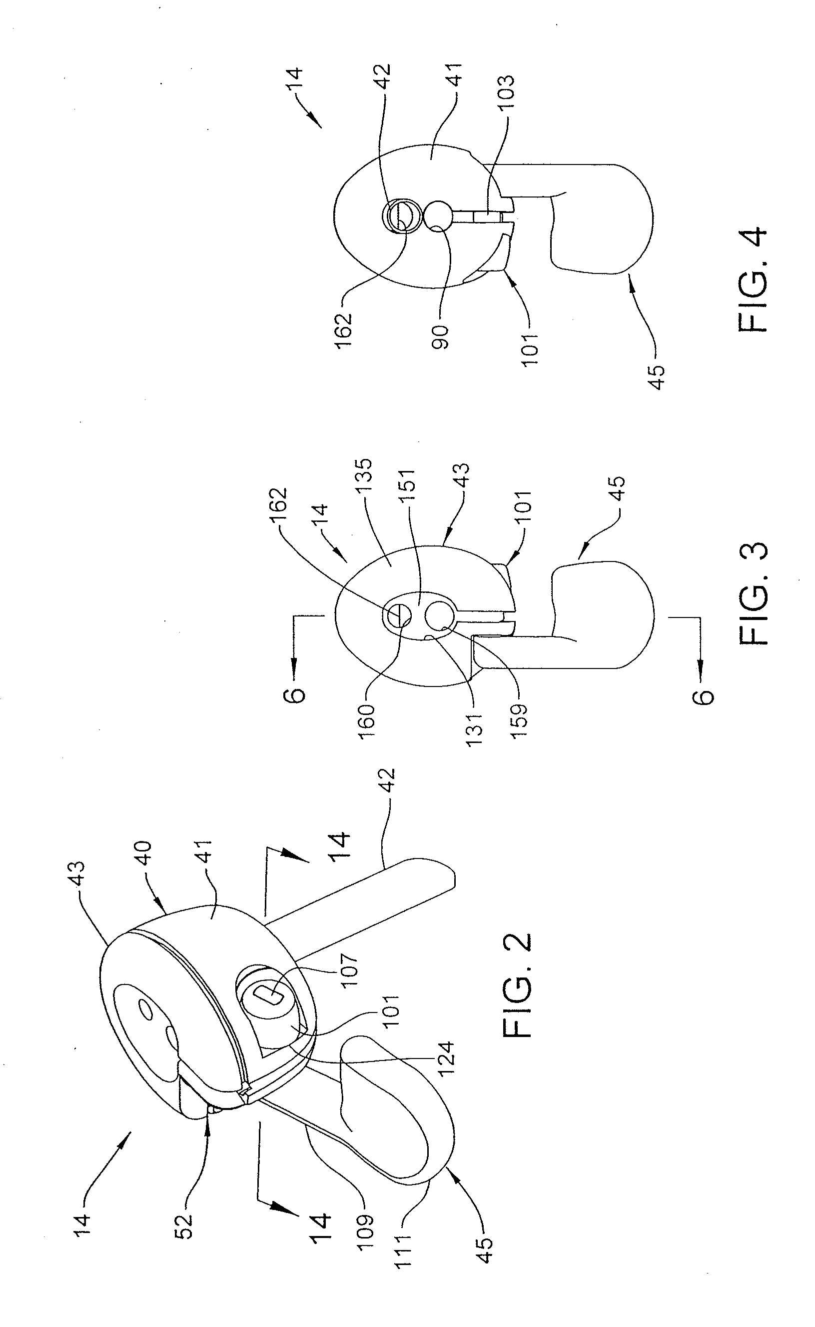
[0009]The arrangement in some embodiments additionally includes a clamping or locking arrangement which cooperates with at least one of the channels defined in the housing so as to non-movably fix the surgical instrument located within the channel relative to the housing and / or at the proper location within and relative to the surgical site. According to a preferred usage of the arrangement, one of the surgical instruments is an endoscope assembly including an elongated shaft which is inserted in the aforementioned channel or scope channel, and when located at the proper depth or location relative to the housing and / or surgical site, the clamping arrangement is engaged so as to fix the endoscope assembly at the selected position. A further surgical instrument, such as a shaver, burr or drill, for example, is inserted into the opposite or working channel defined in the housing and can be utilized to manipulate tissue at the surgical site. In this regard, the working or distal end of the shaver or other instrument must be placed and maintained within the field of view of the endoscope so that the surgeon can correctly manipulate the instrument and carry out the surgical procedure. In this regard, one embodiment of the invention incorporates an elongate channel member which is cantilevered from the housing in a position so as to communicate with, and form an extension of, the working channel through which the shaver or other tissue-manipulating instrument extends. The length of the channel member as well as the orientation of same relative to the scope channel defined in the housing is such that the tissue-manipulating instrument can be readily placed and maintained in the field of view of the endoscope during the surgical procedure.
[0010]The arrangement according to one embodiment of the invention incorporates a sealing arrangement so as to prevent undesirable fluid leakage from the surgical site and also to help maintain in-joint pressure when the arrangement is utilized in arthroscopic surgery, for example. In a further embodiment, the seal arrangement and channel member are dispensed with which provides more flexibility in positioning the surgical instrument by allowing the surgeon to achieve a greater angle of deviation between the surgical instrument and the endoscope.

Problems solved by technology

Further, during multiple-portal endoscopic surgery, surgical instruments, such as the blade of a surgical shaver or an RF probe, may collide with the endoscope optics, which can damage the endoscope and / or potentially cause a delay in surgery.
Additionally, it can be difficult for surgeons to maintain the proper location of the endoscope within the surgical site during surgery.
One of the challenges presented by single-port surgical procedures is preventing stretching and / or tearing of the incision defining the single portal as the surgical instruments are manipulated and levered relative to the patient while same extend into the patient through the portal.

Method used


Image

  • Arrangement for minimal access surgery
  • Arrangement for minimal access surgery
  • Arrangement for minimal access surgery

Examples


third embodiment

[0093]A further or third embodiment of the access and positioning arrangement is illustrated in FIGS. 30-32. Components which are identical or similar to components of the access and positioning arrangement 14 discussed above are provided with the same reference numbers, plus 600. Arrangement 614 includes a hub assembly 640 including a generally hollow hub 641, a working channel 642 which is fixed to and projects from a bottom of hub 641, and a lid or cover 643 which closes off the open upper end of hub 641. Unlike arrangement 14, arrangement 614 does not include a locking arrangement 45, and outer housing wall 650 of arrangement 614 has no recesses 52 and 76, and is instead rounded in these areas similar to the opposite side of the housing wall 650 adjacent working channel 642. As in arrangement 14, housing wall 650 is split so as to define a slot 670 which extends radially outwardly from, and communicates with, clamp opening 690. In the illustrated embodiment, clamp opening 690 is...

fourth embodiment

[0095]An additional or fourth embodiment of the access and positioning arrangement is illustrated in FIGS. 33 and 34. Components of access and positioning arrangement 814 which are similar or identical to components of arrangement 14 are provided with the same reference numbers, plus 800. Arrangement 814 includes a hub assembly 840, a working channel 842 fixed to hub 841 of hub assembly 840, and a cover 843 which closes off the upper end of hub 841. In this embodiment, no locking arrangement 45 is provided, housing wall 850 of hub 841 is not recessed (as is housing wall 50 at 52 and 76) and is not split or slotted (as is housing wall 50 at 70), and instead housing wall 850 is continuously rounded and closed on the side there of opposite channel member 842. Similarly, cover or lid 843 is not slotted as in prior embodiments, and instead is closed. As best shown in FIG. 34, housing wall 850 of hub 841 defines a pair of annular and vertically-spaced channels 1000 which open inwardly and...


PUM


Abstract

An access and positioning arrangement for use during an endoscopic surgical procedure in which a pair of surgical tools are utilized, such as an endoscopic imaging device for providing an image of the surgical site and a surgical instrument for manipulating tissue at the surgical site. The arrangement includes a housing for positioning over a surgical portal defined in the patient through which the surgical site is accessed, which housing defines first and second channels which receive the respective surgical tools so that the tools can be maintained in a fixed orientation relative to one another within the surgical site and so that the tools can be readily positioned in the correct positions relative to one another at the surgical site.

Description

CROSS REFERENCE TO RELATED APPLICATION[0001]This claims the benefit of U.S. Provisional Application No. 61 / 573,280, filed Sep. 2, 2011, the disclosure of which is hereby incorporated by reference in its entirety.FIELD OF THE INVENTION[0002]The present invention relates to an arrangement for performing endoscopic minimal access surgery in conjunction with multiple surgical instruments, one of which may include an imaging apparatus, such as an endoscope.BACKGROUND OF THE INVENTION[0003]Endoscopy is a minimally invasive surgical procedure which utilizes imaging apparatus for the purpose of providing a view of an interior portion of the body, without requiring that a large surgical opening be made in the patient to gain access to the surgical site. An endoscope is one type of such imaging apparatus which is placed in the body at the location at which it is necessary to perform a surgical procedure. Along with the endoscope, other types of surgical tools or instruments may be placed in t...

Claims


Application Information

Patent Timeline
Patent Type & Authority Applications(United States)
IPC IPC(8): A61B1/018A61B1/04
CPCA61B17/3421A61B17/3462A61B2017/3492A61B2017/3447A61B2017/347A61B2017/3445
Inventor FOUTS, BRIANCOOPER, DANIEL E.COVER, REIDBAYCURA, MICHAEL
Owner STRYKER CORP
Why Eureka
Try Eureka