Method for detecting objects

a detection method and object technology, applied in the field of devices and methods for detecting objects, can solve the problems of obtaining a substantial reduction in the overall information of the received signal, and allowing partial drops

Active Publication Date: 2015-03-17
ROBERT BOSCH GMBH
View PDF14 Cites 6 Cited by
  • Summary
  • Abstract
  • Description
  • Claims
  • Application Information

AI Technical Summary

Benefits of technology

[0005]It is the objective of the present invention to provide a method and a device for forming object hypotheses with the aid of a received signal by at least one receiver, the method and the device being designed simply and reliably in measurement technology, which makes possible a rapid and accurate analysis for forming object hypotheses.
[0006]According to the present invention it is provided that the received signal of the reflected wave be divided up into segments, and from the individual segments, additional data being gathered that are drawn upon for the determination of an object hypothesis. Because of this, a simple and rapid processing of the individual segments is made possible, and in addition, the parallel processing of the individual segments may be taken into consideration.
[0007]It is of particular advantage that the individual segments are subdivided over time. A subdivision over time of the received signal, in this instance, is conceivable into equally long and / or unequally long segments. Because of that, the received signal of the reflected wave may be extracted in firmly defined partial signals, so that investigation of the partial, signals is made easier. In addition, observation of significant features of the received signal is possible. Furthermore, the possibility opens up of dropping partial signals, that have no high information content, without obtaining a substantial reduction in the overall information of the received signal. Because of that, efficient and rapid processing and investigation of the received signal disassembled into partial signals may be ensured. It is additionally conceivable that the signal curve of the received signal is subdivided into individual segments. Thus, data may be ascertained over a certain time interval within a specified boundary region, which permit additional evidence on the information content of the received signal. In addition, the specified boundary region may also be limited in time, so that, in the near region of an amplitude, the displacement of the received signal may be investigated more accurately. In addition, the received signal may be subdivided into two-dimensional areas of any size, by subdividing the abscissa and the ordinate into any boundary regions, so that the received signal is able to be disassembled into partial pieces of any size that are able to be drawn upon for closer investigation on their information content. In order to obtain particularly usable received signals of objects that are at a distance of more than 10 m from the receiver, one may advantageously use electromagnetic transmitters for the emission of transmitting pulses. For distances of objects below 10 m, ultrasonic waves have proven to be especially expedient.

Problems solved by technology

Furthermore, the possibility opens up of dropping partial signals, that have no high information content, without obtaining a substantial reduction in the overall information of the received signal.

Method used


Image

  • Method for detecting objects
  • Method for detecting objects
  • Method for detecting objects

Examples


Embodiment Construction

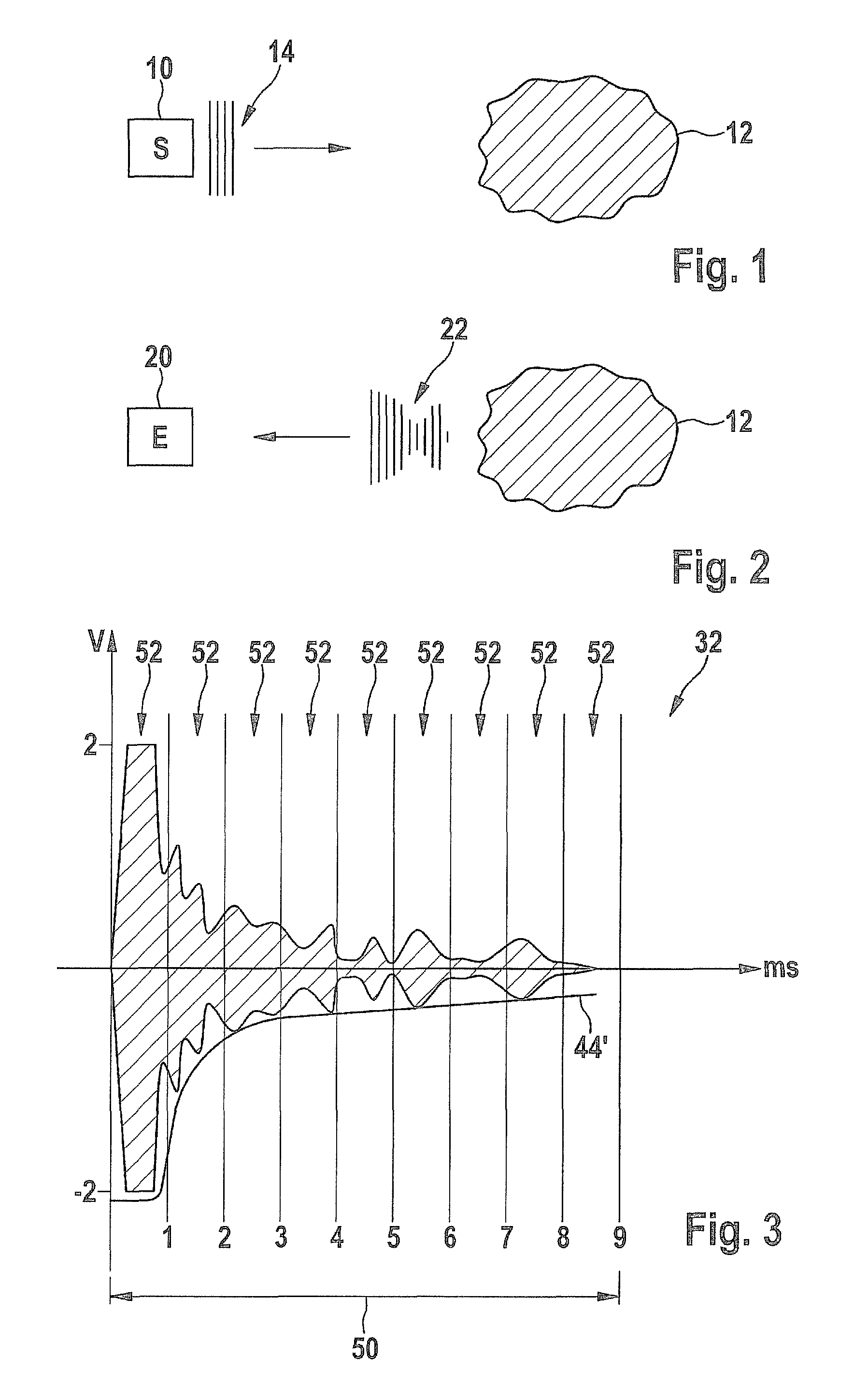
[0023]FIG. 1 schematically shows a transmitter 10, for instance, for ultrasonic waves or electromagnetic waves, which emits a transmitting pulse 14 into a propagation space, in which there is an object 12. Transmitting pulse 14 may vary in its intensity, so that various amplitudes are able to be used. In addition, it is possible to emit various transmitting pulse lengths. Furthermore, the use of several transmitters 10 is conceivable, which emit transmitting pulses that are simultaneous or offset in time. A variation in the frequencies at which the transmitting pulses are emitted is also possible. In this context, setting up transmitters 10 is independent from a specified geographic position or of the corresponding receivers.

[0024]In FIG. 2, a receiver 20 is shown, for example, which is used for measuring reflection signals. An object 12, which is hit by a transmitting pulse 14, causes a reflected wave 22 which is radiated back into the propagation space. Receiver 20 is in a positio...


PUM


Abstract

In a method for detecting objects, at least one sensor emits a transmitting pulse as a wave, particularly as an acoustic or an electromagnetic wave, which wave is reflected at least partially by objects in the propagation space, and the reflected wave being detected by at least one receiver as a received signal. The received signal of the reflected wave is divided up into segments, and from the individual segments, data are gathered that are drawn upon for the determination of an object hypothesis.

Description

BACKGROUND OF THE INVENTION[0001]1. Field of the Invention[0002]The present invention relates to a device and a method for detecting objects, at least one transmitter emitting a transmitting pulse as a wave, which is reflected at least partially by objects in the propagation space; the reflected wave being detected by at least one receiver as a received signal.[0003]2. Description of Related Art[0004]From published German patent application document DE 10 2007 024 641 A1 it is known that sensor data from a plurality of different sensor signal currents detected for a measuring space are drawn upon to form object hypotheses. In this context, any objects, particularly movable objects, such as animals and persons, are detected. However, these signal currents have to be comprehensively evaluated and weighted, which calls for a high technical effort.BRIEF SUMMARY OF THE INVENTION[0005]It is the objective of the present invention to provide a method and a device for forming object hypothes...

Claims


Application Information

Patent Timeline
Patent Type & Authority Patents(United States)
IPC IPC(8): G01S13/04G01S15/04G01S7/41G01S7/539
CPCG01S7/412G01S7/539G01S7/417G01S15/86G01S15/931
Inventor BARTHEL, PAULHAGENMEYER, LORENZMUELLER, MARTINMIELENZ, HOLGER
Owner ROBERT BOSCH GMBH
Why Eureka
Try Eureka