
Personal sound amplifier

a personal sound amplifier and amplifier technology, applied in the field of personal sound amplifiers, can solve the problems of inconvenient wear of the pendant unit with the psa, inconvenient use of the pendant unit, and inability to meet the needs of consumers, and overcome the inherent disadvantages of conventional personal sound amplifiers. , the effect of small siz

Active Publication Date: 2015-03-17
VOXX INT CORP
View PDF28 Cites 1 Cited by
  • Summary
  • Abstract
  • Description
  • Claims
  • Application Information

AI Technical Summary

Benefits of technology

[0008]It is still another object of the present invention to provide a personal sound amplifier device, in the form of a hearing aid, which includes an amplifier circuit for amplifying ambient noise, and a wireless communication circuit for wirelessly communicating with an external electronic device, such as a cellular telephone, and which allows the user of the personal sound amplifier device to selectively permit operation of just the amplifier circuit, or allow operation of both the amplifier circuit and the wireless communication circuit.
[0009]It a further object of the present invention to provide a personal sound amplifier which is small in size and convenient to use and which includes the capability of wirelessly communicating with a remote, external electronic device.
[0011]It is another object of the present invention to provide a personal sound amplifier which overcomes the inherent disadvantages of conventional personal sound amplifiers.

Problems solved by technology

The integration of Bluetooth™ radios into PSAs has been problematic due to battery power consumption, output sound interference, and the space required to incorporate a Bluetooth™ circuit within a hearing aid housing also having the PSA circuit.
However, to utilize the Bluetooth™ capabilities, consumers must inconveniently wear the pendant unit along with the PSA.
Conventional pendant units have significantly limited transmission ranges and signal loss problems.

Method used


Image

  • Personal sound amplifier
  • Personal sound amplifier
  • Personal sound amplifier

Examples


Embodiment Construction

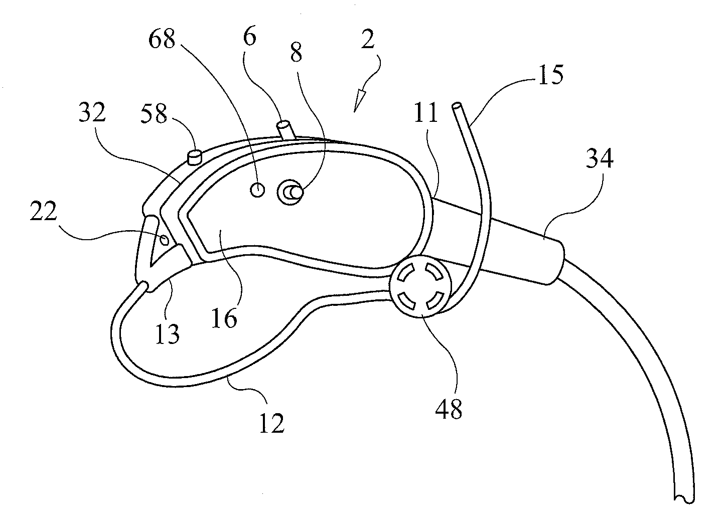
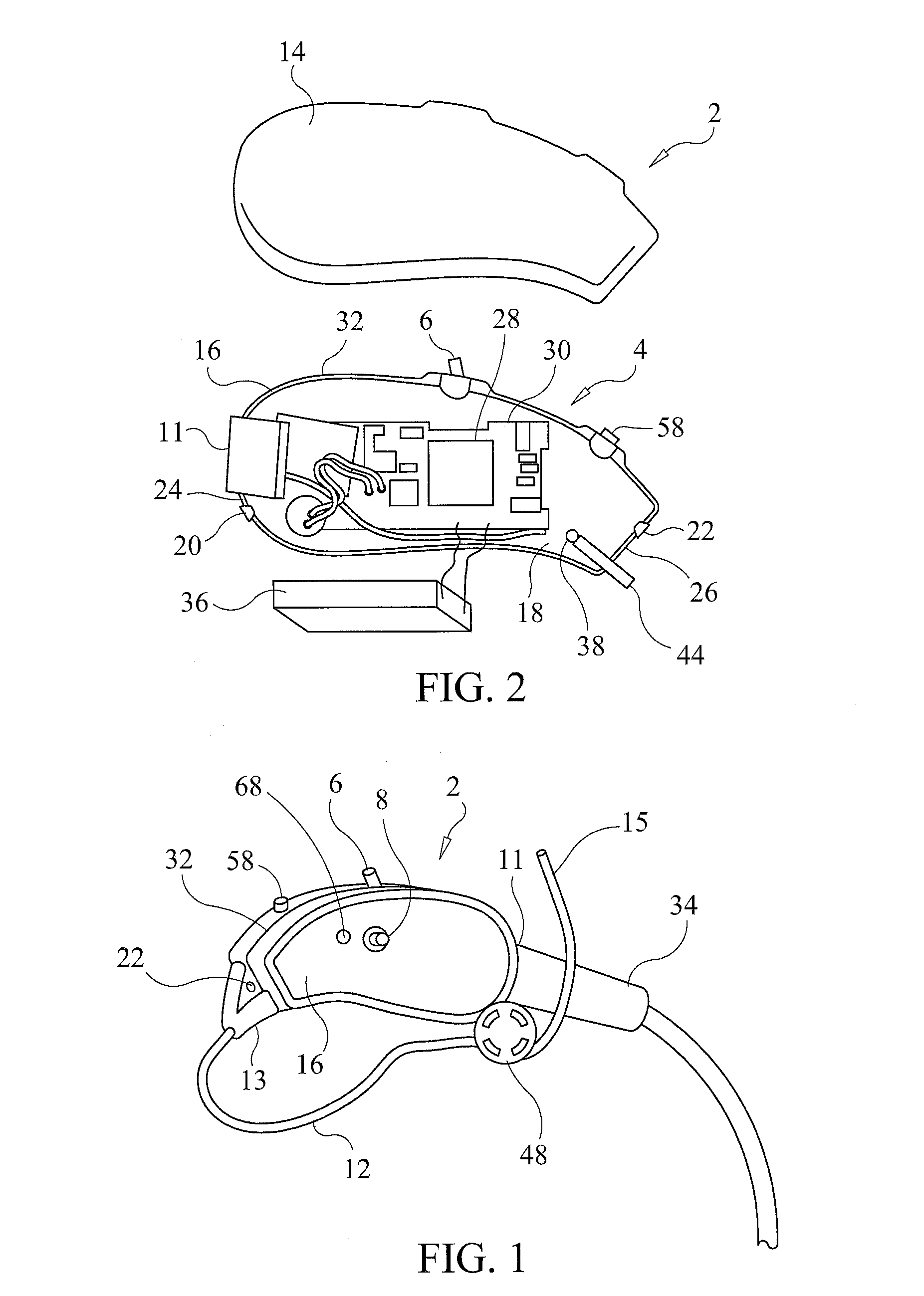
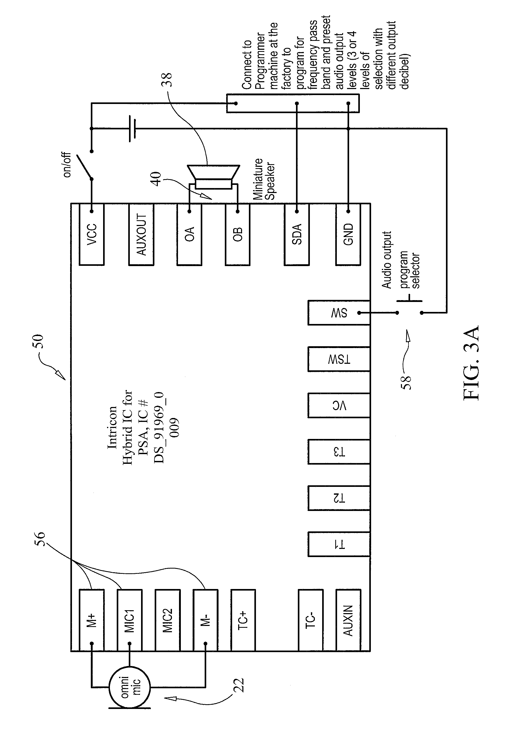
[0021]As can be seen in FIG. 1 of the drawings, a personal sound amplifier 2 constructed in accordance with a preferred embodiment of the present invention includes a main body or housing 4 formed in the shape of a hearing aid (i.e., with a generally arcuate shape) and ergonomically shaped to rest on the ear of a user. The housing or main body 4 is formed from two matable half sections. When mated together, the two sections define an internal cavity for housing the electronic circuit, antenna and battery of the personal sound amplifier 2. The main body 4 has mounted thereon a pair of microphones oriented at opposite lateral ends thereof, a mode selection switch 6, a Bluetooth™ circuit activator switch 8, a micro-USB connector 11 used in conjunction with a battery charging circuit for charging the internal battery, and a hollow hearing tube 12 extending from the main body 4. As will be described in greater detail, the electronic circuit situated in the internal cavity of the main bod...


PUM


Abstract

A personal sound amplifier device in the form of a hearing aid worn by a user not only amplifies sounds but also communicates wirelessly with an external electronic device, such as a cellular telephone. The personal sound amplifier device includes a first microphone, an amplification circuit electrically connected to the first microphone, and a speaker electrically connected to the amplification circuit for amplifying ambient sound detected by the first microphone. A second microphone is situated away from the first microphone. A radio frequency (RF) transmitter and receiver circuit is electrically connected to the second microphone and to the speaker. An antenna is connected to the RF transmitter and receiver circuit. The user's voice is detected by the second microphone and transmitted by the RF transmitter and receiver circuit, through the antenna, to an external electronic device. Signals from the external electronic device are received by the antenna and processed by the RF transmitter and receiver circuit, and are emitted as sound through the speaker for the user to hear.

Description

CROSS-REFERENCE TO RELATED APPLICATIONS[0001]This application is related to U.S. Provisional Application Ser. No. 61 / 584,402, filed on Jan. 9, 2012, and entitled “Personal Sound Amplifier”, the disclosure of which is incorporated herein by reference and on which priority is hereby claimed.BACKGROUND OF THE INVENTION[0002]1. Field of the Invention[0003]The present invention relates to personal sound amplification devices for use by hearing impaired persons, and more particularly relates to personal sound amplification devices having Bluetooth™ functionality.[0004]2. Description of the Prior Art[0005]Conventional personal sound amplifiers (“PSAs”), including hearing aids, do not have integrated Bluetooth™ radios. The integration of Bluetooth™ radios into PSAs has been problematic due to battery power consumption, output sound interference, and the space required to incorporate a Bluetooth™ circuit within a hearing aid housing also having the PSA circuit. To utilize Bluetooth™ technolo...

Claims


Application Information

Patent Timeline
Patent Type & Authority Patents(United States)
IPC IPC(8): H04R25/00
CPCH04R25/554
Inventor TINAPHONG, PRAPAN PAUL
Owner VOXX INT CORP
Learn More