Clothes iron storage case

a storage case and iron technology, applied in the field of iron cases, can solve the problems of inconvenient use, difficult to achieve both easy unlocking operability and lock mechanism malfunction, and achieve the effect of preventing external shock and alleviating the shock of external shock

Active Publication Date: 2015-03-24
PANASONIC INTELLECTUAL PROPERTY MANAGEMENT CO LTD
View PDF14 Cites 1 Cited by
  • Summary
  • Abstract
  • Description
  • Claims
  • Application Information

AI Technical Summary

Benefits of technology

[0020]According to this configuration, it is possible to make the operation for unlocking that lifts up the receiving case easy after moving the operating button outward. Further, it is possible to prevent malfunction of the locking mechanism by alleviate external shock applied to the locking body, by damping the external shock of the receiving case outside the locking body inserted in the locking portion.

Problems solved by technology

However, it is difficult to unlock the locking mechanism when separating the receiving case from the table and it is inconvenient to use.
As a result, the locking mechanism causes the following malfunction.
Therefore, the iron case having the configuration described above has a problem in that it is difficult to achieve both easy unlocking operability when separating a receiving case and at the same time preventing the malfunction in the locking mechanism with respect to the external shock.PTL 1: Japanese Patent Unexamined Publication No. 1-153189PTL 2: Japanese Patent Unexamined Publication No. 7-124397PTL 3: Japanese Patent Unexamined Publication No. 8-89699

Method used


Image

  • Clothes iron storage case
  • Clothes iron storage case
  • Clothes iron storage case

Examples


first exemplary embodiment

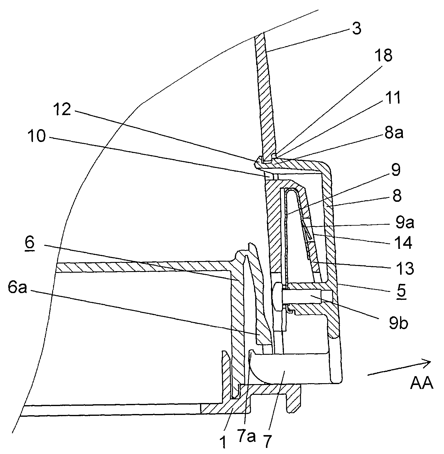
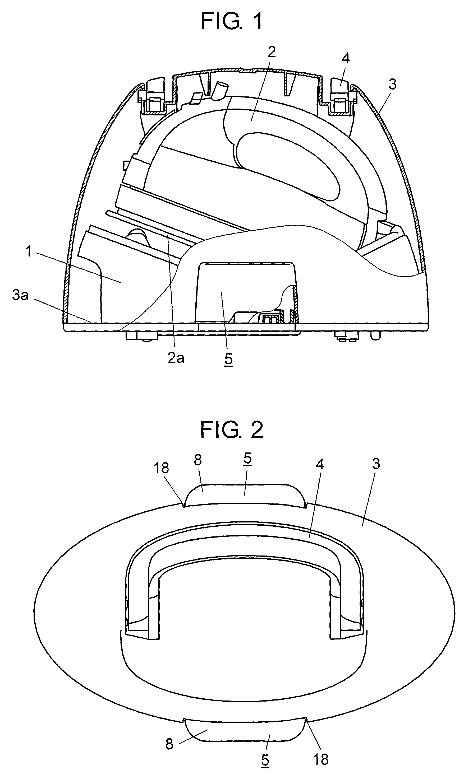
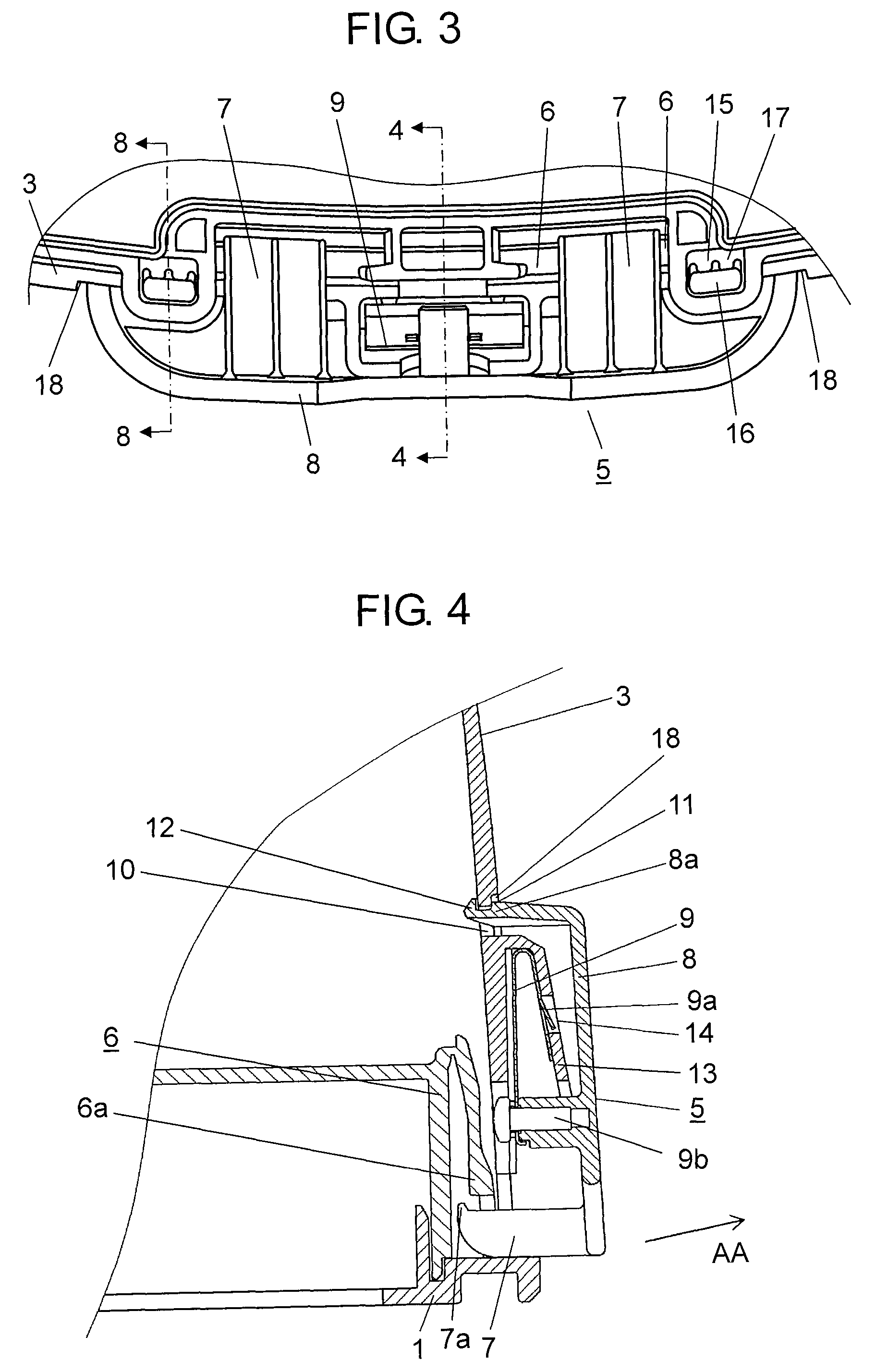
[0031]FIG. 1 is a partial cross-sectional side view of an iron case according to a first embodiment of the present invention. FIG. 2 is a plan view of the iron case. FIG. 3 is a bottom view of the locking mechanism. FIG. 4 is a cross-sectional view taken along the line 4-4 of FIG. 3. FIG. 5 is an operational view of the iron case. FIG. 6 is a view seen from arrow B of FIG. 5. FIG. 7 is an enlarged cross-sectional view of the locking mechanism of the iron case.

[0032]As shown in FIGS. 1 to 7, an iron case includes at least table 1, receiving case 3 with handle 4 at the upper portion, and locking mechanism 5 combining table 1 with receiving case 3.

[0033]Iron 2 is placed on table 1, as shown in FIG. 1, with the front at an angle and underside 2a of iron 2 facing down. Receiving case 3 is made of thermally-resistant thermo-reversible resin, such as ABS resin, and receives iron 2 by surrounding and covering iron 2 placed on table 1 from the upper portion and closing opening 3a disposed in...

second exemplary embodiment

[0051]An iron case according to a second embodiment of the present invention is described hereafter with reference to the drawings.

[0052]FIG. 8 is a cross-sectional view taken along the line 8-8 of FIG. 3, which shows a locking mechanism of an iron case according to a second embodiment of the present invention.

[0053]The embodiment further includes the following configuration, in addition to the configuration of the first embodiment.

[0054]That is, for an iron case according to the embodiment, in locking mechanism 5, engagement hole 15, for example, which has a rectangular shape is formed around locking portion 6 (see FIG. 3) of table 1, for example, engagement portion 16, as shown in FIG. 6, is formed in receiving case 3, opposite engagement hole 15. Recessed fitting portion 18 (see FIG. 3 for detail) where the outer circumferential edge of operating button 8 is fitted is formed on the outer surface of receiving case 3. The other configurations are the same as those of the first embo...


PUM


Abstract

An iron case includes: a table where an iron is placed; a receiving case that surrounds the iron and has a lower opening that is closed by the table; and a locking mechanism that detachably combines the table with the receiving case, in which the locking mechanism includes: a locking portion formed on the sides of the table; a locking body formed at the receiving case and engaged with the locking portion; an operating button disposed to be movable outwardly on the outer surface of the receiving case and operating the locking body; and a locking spring disposed in the receiving case and biasing the operating button to the table. Therefore, malfunction of the locking mechanism is prevented while usability when the receiving case is separated is improved.

Description

[0001]This application is a 371 application of PCT / JP2010 / 007328 having an international filing date of Dec. 17, 2010, which claims priority to JP2009-291722 filed Dec. 24, 2009 and JP2009-291723 filed Dec. 24, 2009, the entire contents of which are incorporated herein by reference.TECHNICAL FIELD[0002]The present invention relates to an iron case that receives an iron.BACKGROUND ART[0003]In the related art, iron cases that receive an iron are generally equipped with a table where an iron is placed, a receiving case that surrounds the iron and has a lower opening closed by the table, and a locking mechanism that combines the table with the receiving case. An example of an iron case having a configuration that prevents the locking mechanism, which combines the table with the receiving case, from being unlocked when the case is lifted and carried (for example, see PTL 1), has been disclosed.[0004]According to the iron case described in PTL 1, a locking mechanism is unlocked by pressin...

Claims


Application Information

Patent Timeline
Patent Type & Authority Patents(United States)
IPC IPC(8): B65D85/00D06F79/00D06F79/02
CPCD06F79/00D06F79/02
Inventor OTSUKA, YASUHARUFUJIMOTO, HIROSHISHIMOSAKA, KIICHIYAGI, TOYOHIKO
Owner PANASONIC INTELLECTUAL PROPERTY MANAGEMENT CO LTD
Why Eureka
Try Eureka