Data migration with source device reuse

Active Publication Date: 2015-03-24
EMC IP HLDG CO LLC
View PDF13 Cites 70 Cited by
  • Summary
  • Abstract
  • Description
  • Claims
  • Application Information

AI Technical Summary

Problems solved by technology

However, one difficulty with the system disclosed in PCT/US2006/024535 and in similar systems is that even after the data has been migrated, proper diversion to the target device

Method used


Image

  • Data migration with source device reuse
  • Data migration with source device reuse
  • Data migration with source device reuse

Examples


Embodiment Construction

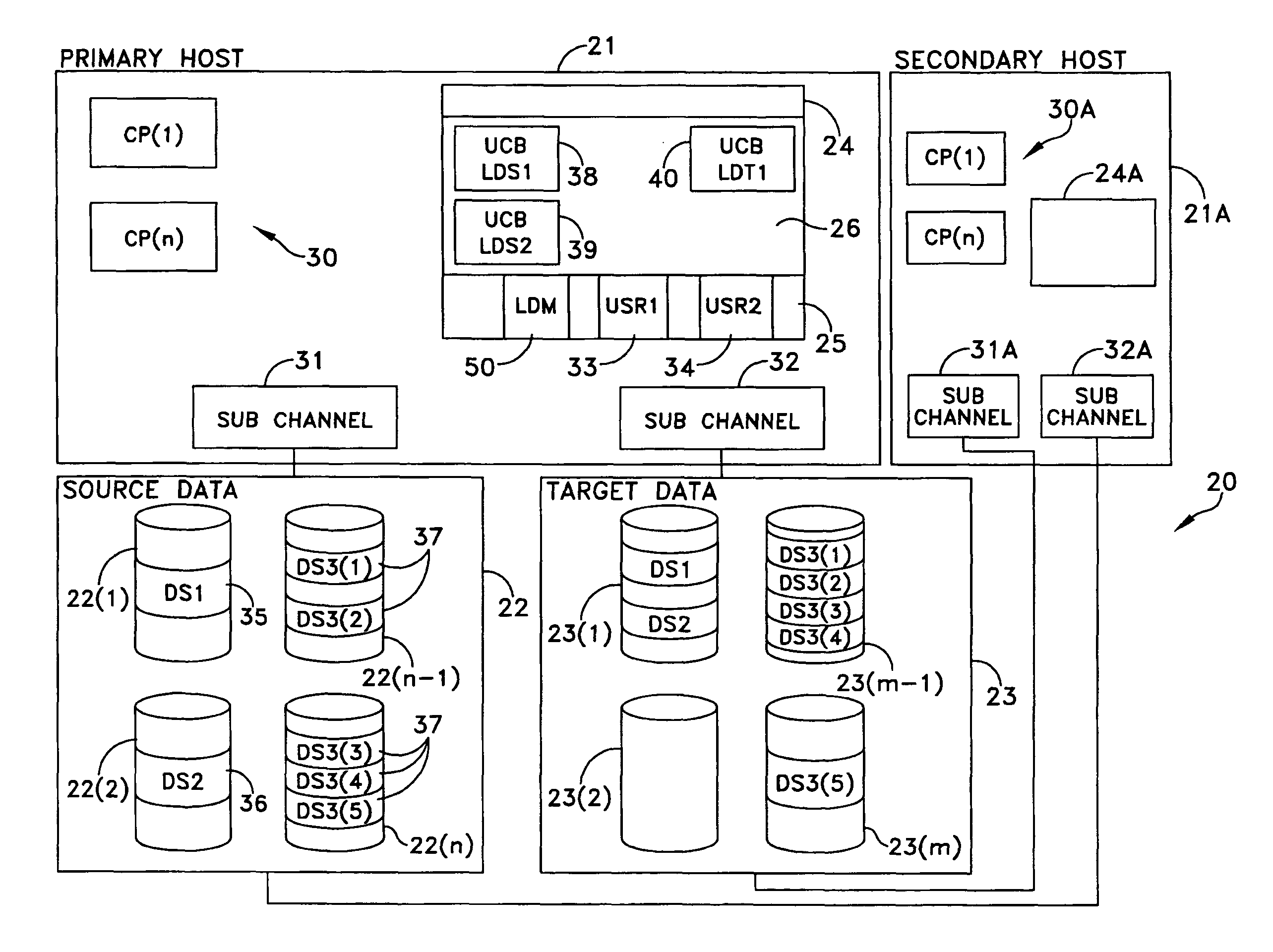
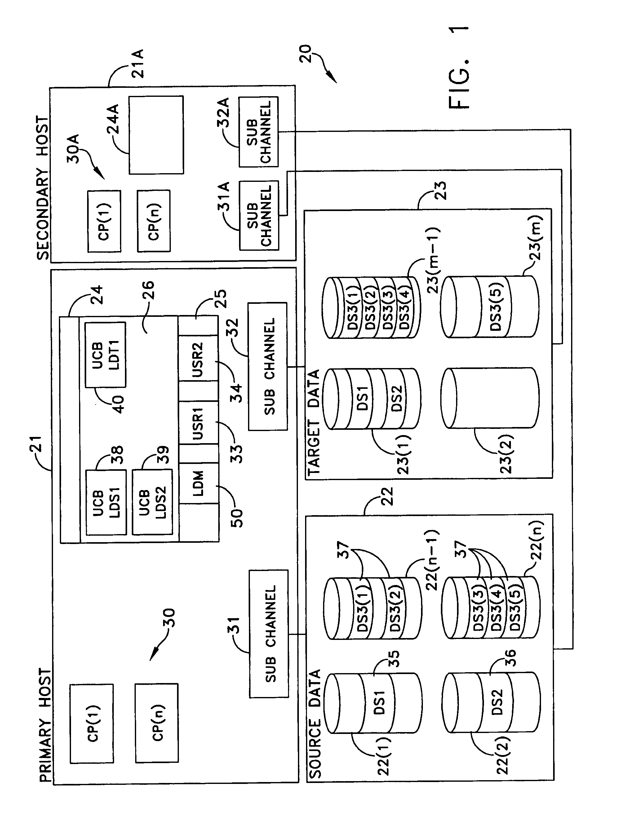
[0043]FIG. 1 depicts, as an example, a data processing system 20 that includes a host 21 and two disk array storage devices as data storage facilities 22 and 23. As known in the art, the host 21 includes a main memory 24 divided into at least one private area 25 and a common storage area 26. One or more processors 30 interact with the memory 24.

[0044]Communications between the single host 21 and input-output devices, such as the data storage facilities 22 and 23, occur through sub-channels. For purposes of explaining this invention, a sub-channel 31 interfaces the host 21 and the source data storage facility 22; a sub-channel 32, the target data storage facility 23. The secondary host 21A has a similar construction with multiple processors 30A, a memory 24A and sub-channels 31A and 32A.

[0045]As previously described, a host application and a data storage facility identify the location of data differently. That is, host applications view data at a logical level as data extents or “ext...


PUM


Abstract

Releasing a data set at a source device in connection with migrating data from the source device to a target device includes mapping application address space to address space containing metadata for the target device and providing additional local metadata therefor, replacing within the application the address of metadata for the source device with the address of metadata for the target device, setting a diversion flag that is part of the additional local metadata, where the diversion flag indicates a remapping of extent, and closing and unallocating the data set at the source device. Releasing a data set at a source device in connection with migrating data from the source device to a target device may also include determining if an application uses standard I/O operations. The metadata may include UCB data.

Description

BACKGROUND OF THE INVENTION[0001]1. Field of the Invention[0002]This invention relates to data storage facilities and more specifically to migrating data between data storage facilities.[0003]2. Description of Related Art[0004]A data storage facility generally comprises a disk array storage device that includes physical storage media and related controls. For example, a typical disk array storage device includes a plurality of physical disk drives as physical storage media. The controls include a cache memory, an interconnecting bus and adapters. At least one host adapter connects between a host processor, or “host” and the bus. A plurality of disk adapters act as interfaces between the bus and the physical disk drives.[0005]From the perspective of applications being processed by a host, disk storage typically is organized into “logical devices”. Such “logical devices” are also known as “logical storage devices”, “logical volumes” and “devices”. The following discussion uses “logica...

Claims


Application Information

Patent Timeline
IPC IPC(8): G06F12/00G06F13/00G06F13/28G06F3/06
CPCG06F3/0617G06F3/0689G06F3/0647G06F3/067
Inventor LINSTEAD, PAUL
Owner EMC IP HLDG CO LLC
Why Eureka
Try Eureka