Charging member, process for its production, and electrophotographic apparatus

a charging member and electrophotography technology, applied in the direction of metal-working apparatus, electrography/magnetography, textiles and paper, etc., can solve the problem of faulty cleaning of the electrophotographic photosensitive member, and achieve the effect of lowering the grade of electrophotographic images

Active Publication Date: 2015-03-31
CANON KK
View PDF29 Cites 24 Cited by
  • Summary
  • Abstract
  • Description
  • Claims
  • Application Information

AI Technical Summary

Benefits of technology

[0006]However, studies made on the charging member according to Japanese Patent Application Laid-Open No. H09-160355 have revealed that such a charging member may cause faulty cleaning on the electrophotographic photosensitive member. Such faulty cleaning coming about on the electrophotographic photosensitive member refers to a phenomenon that any residual toner on the surface of the electrophotographic photosensitive member, which fundamentally should have been removed with an elastic blade, slips through the elastic blade to lower the grade of electrophotographic images formed through subsequent cycles of electrophotographic image formation.
[0007]Accordingly, the present invention is directed to providing a charging member that can not easily cause faulty cleaning on the electrophotographic photosensitive member while having a flexibility high enough to form a nip between it and the electrophotographic photosensitive member in a sufficient width, and provide a process for its production.
[0008]Further, the present invention is directed to providing an electrophotographic apparatus that can stably form high-grade electrophotographic images over a long period of time as it may less cause any lowering of charging performance with time.
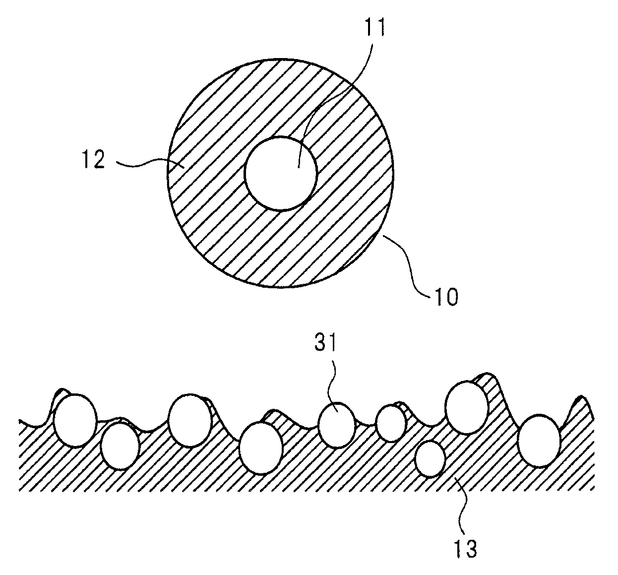
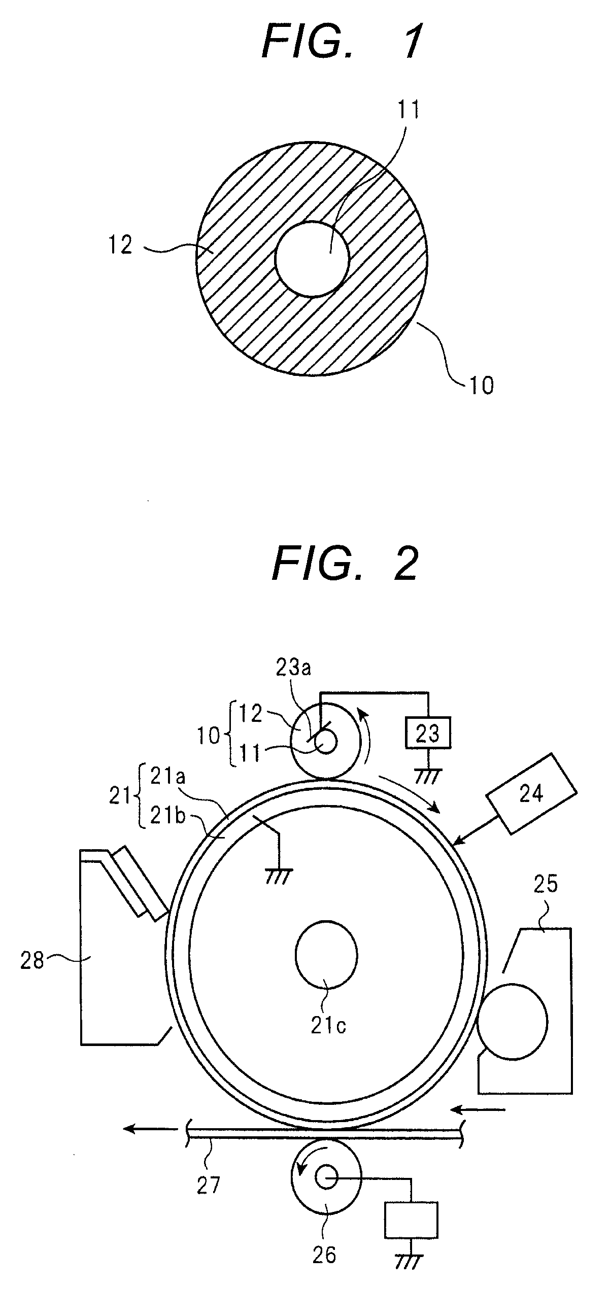
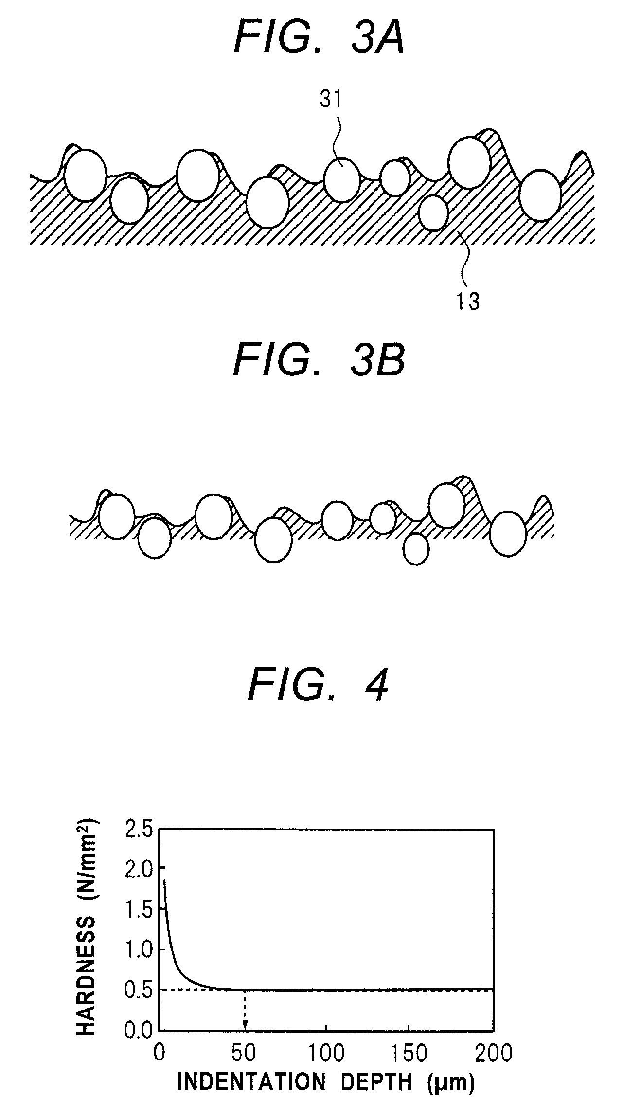
[0009]According to one aspect of the present invention, there is provided a charging member comprising an electro-conductive support and an elastic layer as a surface layer, wherein; the elastic layer has a cured region on the surface of the elastic layer, the cured region having been cured by irradiation with electron rays, the cured region supporting spherical polyethylene particles in such a state that the spherical polyethylene particles are exposed to the surface of the elastic layer, and the surface is thereby roughened.
[0015]According to the present invention, it is able to obtain a charging member having been made to keep any faulty cleaning from coming about while having a flexible surface that is enough to form a nip between it and the electrophotographic photosensitive member in a sufficient width.

Problems solved by technology

H09-160355 have revealed that such a charging member may cause faulty cleaning on the electrophotographic photosensitive member.

Method used


Image

  • Charging member, process for its production, and electrophotographic apparatus
  • Charging member, process for its production, and electrophotographic apparatus
  • Charging member, process for its production, and electrophotographic apparatus

Examples


example 1

Preparation of Unvulcanized Rubber Composition for Elastic Layer

[0092]Materials shown in Table 1 below were mixed by means of a 6-liter pressure kneader (trade name: TD6-15MDX; manufactured by Toshin Co., Ltd.) for 16 minutes in a packing of 70 vol. % and at a number of blade revolutions of 30 rpm to obtain an A-kneaded rubber composition.

[0093]

TABLE 1Part(s)Materialsby massAcrylonitrile-butadiene rubber (NBR)100(trade name: N230SV; available from JSR Corporation)Zinc stearate1Zinc oxide5Calcium carbonate20(trade name: NANOX #30; available from Maruo CalciumCo., Ltd.)Carbon black44(trade name: TOKA BLACK #7400; available from TokaiCarbon Co., Ltd.)Spherical polyethylene particles 1 (spherical PE particles 1)30(trade name: HIZEX MILLION 320MU; available from MitsuiChemicals, Inc.

[0094]Next, materials shown in Table 2 below were mixed by means of an open roll of 12 inches (0.30 m) in roll diameter at a number of front-roll revolutions of 8 rpm and a number of back-roll revolutions of ...

example 2

[0123]A vulcanized rubber roller having been sanded was produced in the same way as Example 1 except that the spherical PE particles 1 used in the A-kneaded rubber composition of Example 1 were changed for spherical PE particles 2 (trade name: HIZEX MILLION 240S; available from Mitsui Chemicals, Inc.) and the spherical PE particles 2 were mixed in an amount of 35 parts by mass. The hardness of its vulcanized rubber layer was measured in the same way as Example 1 to find that it was 78°. Subsequently, the surface of the vulcanized rubber roller having been sanded was subjected to cure treatment by irradiation with electron rays in the same way as Example 1 to produce a charging roller, and the measurement of its cure treatment thickness, the measurement of its surface roughness and the image evaluation were made alike.

example 3

[0124]An unvulcanized rubber composition for elastic layer was prepared and a vulcanized rubber roller having been sanded was produced both in the same way as Example 2 except that the polymer (raw material) used in the A-kneaded rubber composition of Example 2 was changed for 55 parts of NBR and 45 parts of SBR (trade name: TOUGHDEN 2000; available from Asahi Kasei Chemicals Corporation) and the spherical PE particles 2 were mixed in an amount changed to 30 parts by mass. The hardness of the vulcanized rubber layer of the vulcanized rubber roller having been sanded was measured in the same way as Example 2 to find that it was 76°. Subsequently, the surface of the vulcanized rubber roller having been sanded was subjected to cure treatment by irradiation with electron rays in the same way as Example 2 to produce a charging roller, and the measurement of its cure treatment thickness, the measurement of its surface roughness and the image evaluation were made alike.


PUM

PropertyMeasurementUnit
length-average particle diameteraaaaaaaaaa
thicknessaaaaaaaaaa

Abstract

To provide a charging member that can not easily cause faulty cleaning on a photosensitive member while having a flexibility high enough to form a nip between it and the photosensitive member in a sufficient width. The charging member has an electro-conductive support and an elastic layer that is a surface layer, which elastic layer has at its surface a region having been cured by irradiation with electron rays, where this region supports spherical polyethylene particles in such a state that the spherical polyethylene particles are exposed to the surface of the elastic layer, thereby making the surface roughened.

Description

CROSS-REFERENCE TO RELATED APPLICATIONS[0001]This application is a continuation of International Application No. PCT / JP2012 / 005674, filed Sep. 7, 2012, which claims the benefit of Japanese Patent Application No. 2011-281780, filed Dec. 22, 2011.BACKGROUND OF THE INVENTION[0002]1. Field of the Invention[0003]This invention relates to a charging member used in electrophotographic apparatus and the like, a process for its production, and an electrophotographic apparatus.[0004]2. Description of the Related Art[0005]In electrophotographic image forming apparatus, it is common that a charging member used in the contact charging of a photosensitive member or the like is provided with an elastic layer containing a rubber, a thermoplastic elastomer or the like, in order to secure a uniform nip between it and such a charging object member and prevent the charging object member from being scratched. However, a toner and its external additives tend to adhere to the surface of such an elastic la...

Claims


Application Information

Patent Timeline
Patent Type & Authority Patents(United States)
IPC IPC(8): B23P17/00G03G15/02F16C13/00B05D5/00G03G5/02
CPCG03G5/02G03G15/0233B05D5/00C08L9/02C08L9/06C08K3/04C08K3/26C08L23/04Y10T428/24405Y10T29/4956Y10T29/49563
Inventor WATANABE, HIROAKIHARADA, MASAAKIFURUKAWA, TAKUMINOSE, KEIJITERADA, KENYA
Owner CANON KK
Why Eureka
Try Eureka