Peristaltic pumps

a technology of peristaltic pumps and flexible tubing, which is applied in the direction of positive displacement liquid engines, intravenous devices, suction devices, etc., can solve the problems of premature wear of flexible tubing, and achieve the effect of reducing friction forces

Active Publication Date: 2020-06-23
HODGES & DRAKE DESIGN LTD
View PDF33 Cites 0 Cited by
  • Summary
  • Abstract
  • Description
  • Claims
  • Application Information

AI Technical Summary

Benefits of technology

[0009]wherein the radially deformable ring includes a ring anchor for preventing rotation of the radially deformable ring during rotation of the rotor.
[0017]In a conventional peristaltic pump, the flexible tubing is subjected to high rates of wear because of the friction forces applied by the pressing members during rotation of the rotor. It is, therefore, generally necessary to use expensive high-grade flexible tubing that can withstand the high friction forces to avoid premature wear of the flexible tubing. In the peristaltic pump according to the present disclosure, the radially deformable ring prevents direct contact between the pressing members and the flexible tubing, the radial compression force instead being applied to the flexible tubing by the radially deformable ring. As a result, the flexible tubing does not wear out during operation of the pump. In addition, the flexible tubing is not stretched or pinched because the radially deformable ring is held stationary by the ring anchor. This means that lower grade (and, therefore, less expensive) flexible tubing can typically be used.
[0018]The rotor may be engageable by an external rotary drive. With this arrangement, the peristaltic pump is easy and cheap to manufacture and can be readily provided as a disposable system. In particular, because the rotary drive is a separate component that engages the rotor of the peristaltic pump, the peristaltic pump has a simple and inexpensive construction which can, for example, be formed integrally with or attached to a liquid container and which can be disposed of with the liquid container, for example when the container is empty.
[0019]The inlet side and the outlet side of the flexible tubing may be arranged side-by-side, at circumferentially adjacent positions on the cylindrical stator, so that the flexible tubing may extend in a substantially radial direction outwardly away from the cylindrical stator. The ring anchor may project radially outwardly from the deformable ring and may be located between the inlet side and the outlet side of the flexible tubing. The ring anchor may be gripped between the inlet side and the outlet side of the flexible tubing. The ring anchor may comprise a finger projecting radially outwardly from the radially deformable ring. This arrangement provides a convenient way to prevent rotation of the radially deformable ring.
[0021]The radially deformable ring may include a plurality of circumferentially-spaced radial projections on a first axial rim which may project in a radially outward direction towards the inner wall of the cylindrical stator. The radial projections may help to axially retain the flexible tubing on the radially deformable ring, in particular whilst the flexible tubing and the radially deformable ring are being positioned in the cylindrical stator during assembly of the peristaltic pump.
[0022]The rotor may include a circular flange which may axially retain the flexible tubing and the radially deformable ring in the cylindrical stator. In an embodiment, the radially deformable ring may be arranged in the stator with the radial projections in contact with the circular flange. In this embodiment, the radial projections act as plain bearing members and space the flexible tubing from the axially inner surface of the rotating circular flange. This reduces friction forces between the rotating circular flange and the static flexible tubing as the rotor rotates and prevents the flexible tubing from being gripped and stretched by the circular flange during rotation of the rotor.

Problems solved by technology

The friction between the pressing members and the tubing can, however, cause a number of problems, notably premature wear of the flexible tubing, and the present disclosure seeks to address this.

Method used


Image

  • Peristaltic pumps
  • Peristaltic pumps
  • Peristaltic pumps

Examples


first embodiment

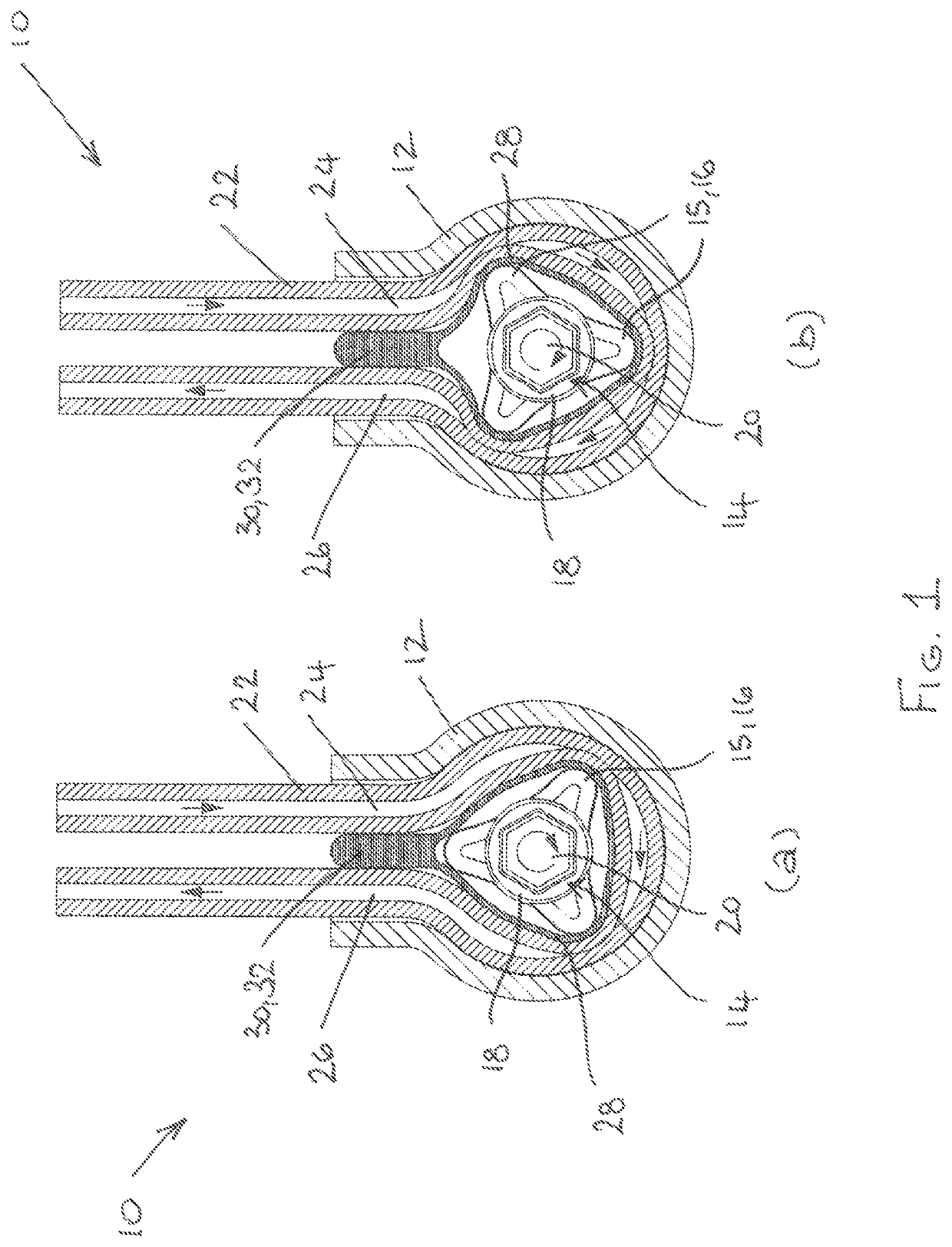
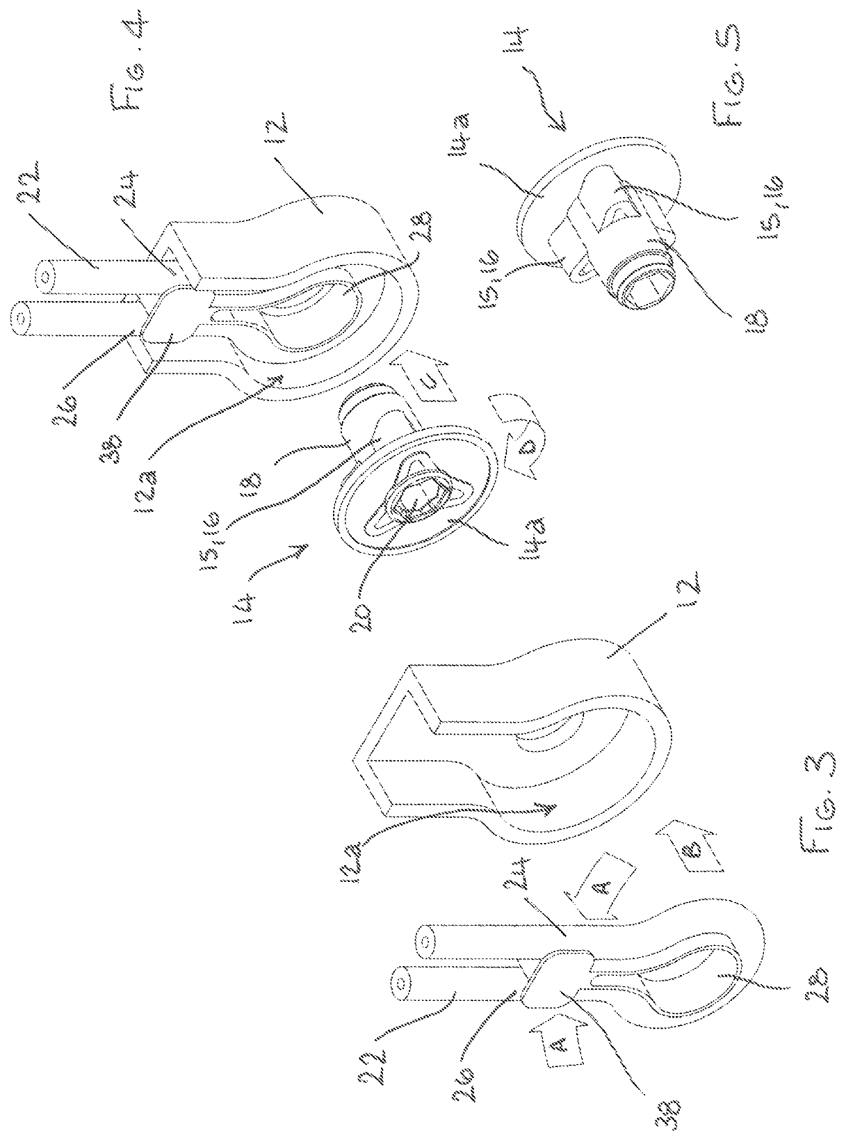
[0040]FIGS. 1 to 5 illustrate a peristaltic pump 10 which includes a rotor 14 (best seen in FIG. 5), typically formed of a moulded substantially rigid plastics material. The rotor 14 includes a plurality of pressing members 15 in the form of lobes 16 which are integrally formed with, and project radially outwardly from, a spindle 18 and which are equally spaced around the circumference of the spindle 18. In the illustrated embodiment, the rotor 14 includes three lobes 16 but it will be appreciated that the rotor 14 can include any suitable number of lobes 16. The spindle 18 includes a central drive aperture 20 which can be engaged by an external rotary drive (not shown) such as the drive shaft of an electric motor.

[0041]The peristaltic pump 10 includes flexible tubing 22 which can be formed of any suitable resilient plastics material such as polyvinyl chloride. The flexible tubing 22 has an inlet side 24 through which liquid is delivered to the peristaltic pump 10 and an outlet side...

second embodiment

[0049]Referring now to FIGS. 6 to 12, there is shown a peristaltic pump 50. The peristaltic pump 50 shares many features in common with the peristaltic pump 10 illustrated in FIGS. 1 to 5 and corresponding features are designated using corresponding reference numerals. The differences between the peristaltic pumps 10, 50 will now be explained.

[0050]The peristaltic pump 50 includes a rotor 52 (best seen in FIG. 11) which includes two diametrically opposed lobes 54 that are integrally formed with, and project radially outwardly from, the spindle 18. As best seen in FIGS. 6a and 6b, each lobe 54 has a curved or arcuate pressing surface 54a whose radius relative to the spindle axis increases gradually and smoothly. The pressing surface 54a progressively compresses the flexible tubing 22 against the inner wall 12a of the cylindrical stator 12 as the rotor 52 rotates in the cylindrical stator 12 in the clockwise direction. Each lobe 54 also has an apex 54b at which the pressing surface 54...


PUM


Abstract

A peristaltic pump (10) comprises a drivable rotor (14), having at least one pressing member (15), and a cylindrical stator (12) in which the rotor (14) is rotatable. Flexible tubing (22), having an inlet side (24) and an outlet side (26), extends circumferentially around the cylindrical stator (12) against an inner wall (12a). The peristaltic pump (10) includes a radially deformable ring (28) positioned between the rotor (14) and the circumferentially extending flexible tubing (22). The ring (28) is deformed by the pressing member (15) upon rotation of the rotor (14) and this compresses the flexible tubing (22) against the inner wall (12a) of the cylindrical stator (12) to convey liquid along the flexible tubing (22). The radially deformable ring (28) includes a ring anchor (30) which prevents rotation of the radially deformable ring (28) during rotation of the rotor (14).

Description

TECHNICAL FIELD[0001]The present disclosure relates generally to peristaltic pumps.TECHNICAL BACKGROUND[0002]Peristaltic pumps are used to pump liquids in a wide variety of applications, in particular where the flow of liquid needs to be carefully metered and where contamination of the liquid needs to be avoided. They are extensively used in medical applications, for example to deliver intravenous (IV) liquids to a patient, and also in food and beverage applications, for example to dispense a predetermined quantity of a beverage or a component of a beverage such as a liquid flavouring.[0003]In a conventional peristaltic pump, flexible tubing is compressed between the pressing members (e.g. pins or rollers) of a rotor and a stator, and liquid is conveyed through the flexible tubing as the rotor rotates. The friction between the pressing members and the tubing can, however, cause a number of problems, notably premature wear of the flexible tubing, and the present disclosure seeks to a...

Claims


Application Information

Patent Timeline
Patent Type & Authority Patents(United States)
IPC IPC(8): F04B43/12F04B43/00
CPCF04B43/1253F04B43/0072F04B43/1261F04B43/1276F04B43/123A61M60/279F04B43/12
Inventor HODGES, KEVIN
Owner HODGES & DRAKE DESIGN LTD
Why Eureka
Try Eureka