Multiple action hoist

a hoist and multi-action technology, applied in the field of hoists, can solve the problems of high cost, high difficulty, and dangerous, and achieve the effect of efficient, convenient, and safe use of the end of the hois

Inactive Publication Date: 2015-03-31
HERMAN ANDREW
View PDF8 Cites 6 Cited by
  • Summary
  • Abstract
  • Description
  • Claims
  • Application Information

AI Technical Summary

Benefits of technology

[0005]Another object is to provide a unitary hoist as characterized above which may be more efficiently, easily, and safely used in transferring the ends of power lines between different support locations.
[0006]A further object is to provide such a hoist of the above kind which eliminates the need for a separate second hoist in the transfer of power lines between support locations.
[0008]Still a further object is to provide a method for more efficiently and safely transferring the ends of power lines from one support location to another.

Problems solved by technology

It often is necessary to transfer the ends of such power lines from one support post to another due to damage, aging, or rotting of the post material.
Since the power lines typically are maintained in high tension, the handling of separate hoists by a workman high on the support post can be highly cumbersome, difficult, and dangerous.

Method used


Image

  • Multiple action hoist
  • Multiple action hoist
  • Multiple action hoist

Examples


Embodiment Construction

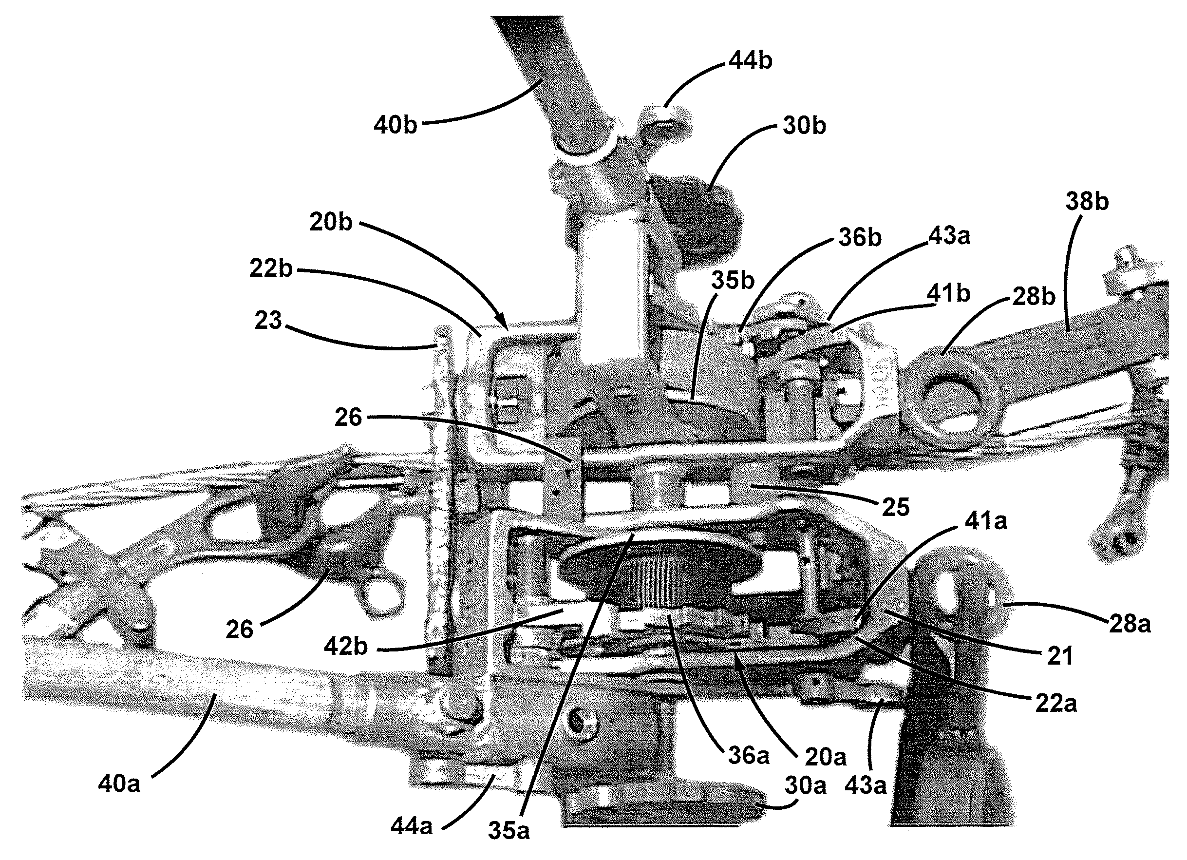
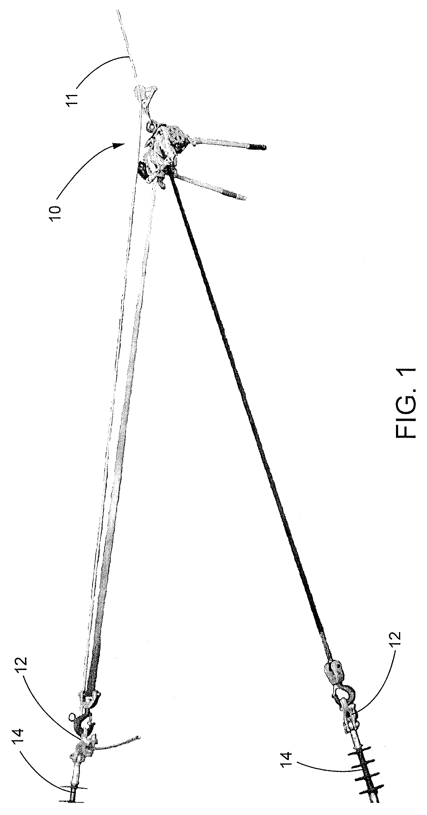
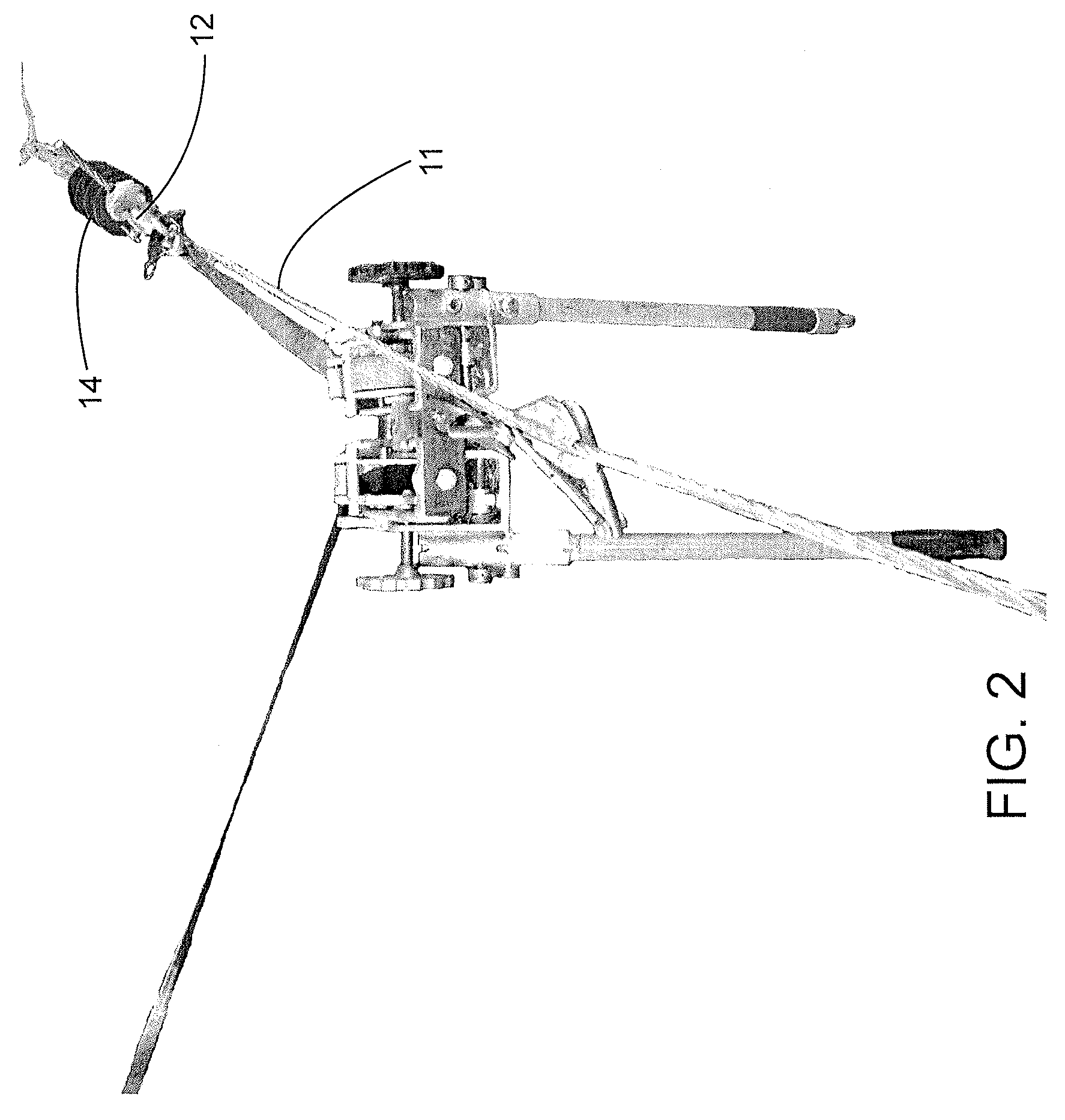
[0019]Referring now more particularly to the drawings, there is shown an illustrative multiple action hoist 10 in accordance with the invention, which is effective for efficiently transferring the end of a power line 11 from one support post to second newly-installed post in relatively closely displaced relation to the original post, or from one support position on a support post to a different support position on the post either vertically or horizontally offset from the original position. As in known in the art, the end of the power line 11 commonly is connected to a support post, or a cross arm of the support post by a dead end connector 12 of a conventional type within which the terminal end of the power line 11 is clamped. The dead end connector 12 in turn is coupled to an insulator 14, again of a known type, which is coupled to the support post or cross arm thereof in a conventional manner, such as by a sister eye bolted to the cross arm.

[0020]For transferring the end of the p...


PUM


Abstract

A method and apparatus for transferring the ends of power lines between first and second supports including a frame having a pair of independently operable hoist mechanisms which each include a tension line with an attachment element at the end thereof, with the drums being rotatable by respective ratchet mechanisms for enabling the transfer of the end of a tension line from one support location to a different support location.

Description

CROSS-REFERENCE TO RELATED APPLICATION[0001]This patent application claims the benefit of U.S. Provisional Patent Application No. 61 / 593,929 filed Feb. 2, 2012, which is incorporated by reference.FIELD OF THE INVENTION[0002]The present invention relates generally to hoists which have particular utility in the transfer of ends of power lines between support posts, and more particularly, to an apparatus and method for transferring the ends of power lines from one support post to a different nearby support post or location of support.BACKGROUND OF THE INVENTION[0003]Power lines are supported in the field by support posts, or cross arms of such support posts, at elevations of 60 feet or more above the ground. It often is necessary to transfer the ends of such power lines from one support post to another due to damage, aging, or rotting of the post material. This commonly is done by hand operated hoists operated by linemen positioned at the elevation of the power line. Typically one hois...

Claims


Application Information

Patent Timeline
Patent Type & Authority Patents(United States)
IPC IPC(8): H02G1/08H02G1/02
CPCH02G1/02
Inventor HERMAN, ANDREW
Owner HERMAN ANDREW
Why Eureka
Try Eureka