Spring-assisted cranial clamp

a technology of cranial clamps and springs, applied in the field of adjustable fasteners, can solve the problems of inability to use rigid fixations, damage to the brain, and harm to the brain,

Inactive Publication Date: 2015-03-31
LERS SURGICAL
View PDF34 Cites 0 Cited by
  • Summary
  • Abstract
  • Description
  • Claims
  • Application Information

AI Technical Summary

Problems solved by technology

This inability to expand in case of post-operative swelling can be harmful to the brain in damaging cerebral tissues due to the increase of intracranial pressure (ICP).
Similarly, these rigid fixations cannot be used when a decompressive craniotomy (to relieve cerebral edema and intracranial hyperpression following a traumatic brain injury) is performed.

Method used


Image

  • Spring-assisted cranial clamp
  • Spring-assisted cranial clamp
  • Spring-assisted cranial clamp

Examples


Embodiment Construction

[0032]It will be readily apparent to one skilled in the art that various embodiments and modifications may be made in the invention disclosed herein without departing from the scope and spirit of the invention.

[0033]Unless defined otherwise, technical and scientific terms used herein have the same meaning as commonly understood by one of ordinary skill in the art to which this invention belongs. For purposes of the present invention, the following terms are defined below.

[0034]As used herein, the use of the word “a” or “an” when used in conjunction with the term “comprising” in the claims and / or the specification may mean “one,” but it is also consistent with the meaning of “one or more,”“at least one,” and “one or more than one.” Some embodiments of the invention may consist of or consist essentially of one or more elements, method steps, and / or methods of the invention. It is contemplated that any method or composition described herein can be implemented with respect to any other ...


PUM


Abstract

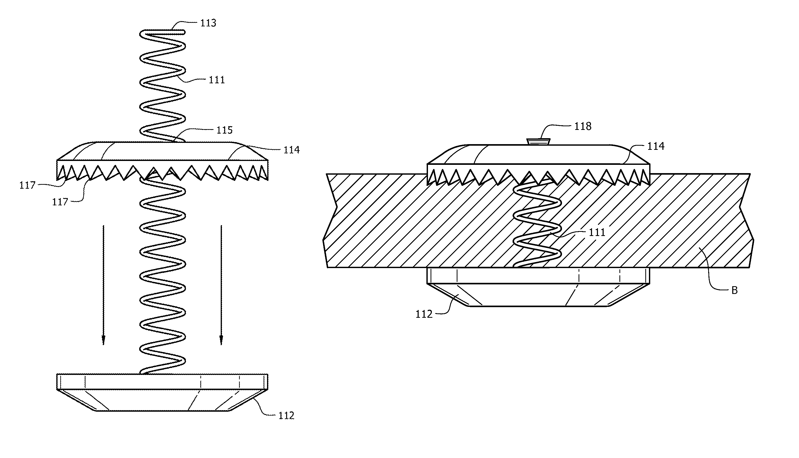
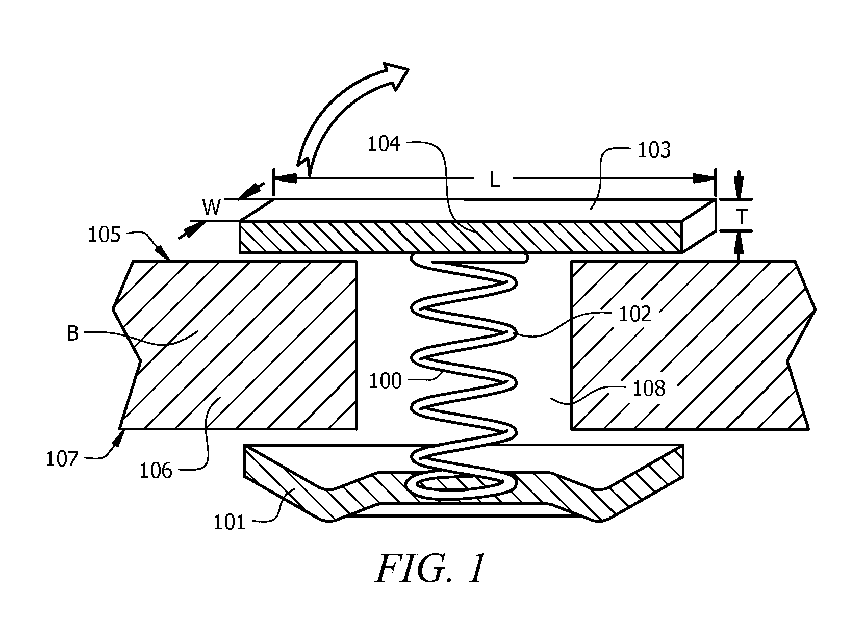
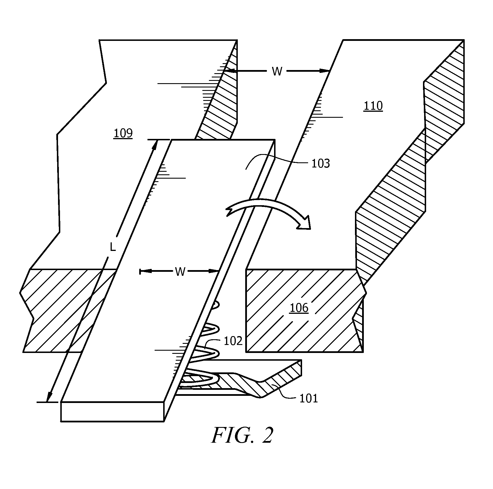
A cranial clamp for attaching a cranial flap to the skull comprises a clamp having a base to be placed against the lamina interna, and a cap acting as a locking member against the lamina externa. The clamp and the cap are linked together by an extension spring within the diploe through a burr hole or along / within the line of a craniotomy.

Description

[0001]The present application is a national phase application filed under 35 USC §371 from PCT / US2008 / 087170, filed Dec. 17, 2008, which claims priority to U.S. Provisional Patent Application Ser. No. 61 / 014,785, filed Dec. 19, 2007, and U.S. Provisional Patent Application Ser. No. 61 / 101,213, filed Sep. 30, 2008, all of which applications are incorporated by reference herein in their entirety.FIELD OF THE INVENTION[0002]This invention relates to a fastener for quickly and securely fastening a cranial bone flap to the surrounding bone, and more particularly to adjustable fasteners that allow for post-operative cerebral edema and intracranial hypertension.BACKGROUND OF THE INVENTION[0003]When performing surgery on the brain, it is often necessary to perform a craniotomy to provide access to portions of the brain. A craniotomy is a surgical procedure in which a portion of the cranial vault is removed to permit access to the brain. To perform the craniotomy, several burr holes are init...

Claims


Application Information

Patent Timeline
Patent Type & Authority Patents(United States)
IPC IPC(8): A61B17/84A61B17/68
CPCA61B17/688Y10S606/903
Inventor SEVRAIN, LIONEL C.
Owner LERS SURGICAL
Why Eureka
Try Eureka