Wrap-around container carrier

a container carrier and wrap-around technology, applied in the field of wrap-around container carriers, to achieve the effect of preserving the structural integrity of the sturdy carrier and not sacrificing the structural integrity of the carrier

Active Publication Date: 2015-04-07
C W ZUMBIEL
View PDF25 Cites 9 Cited by
  • Summary
  • Abstract
  • Description
  • Claims
  • Application Information

AI Technical Summary

Benefits of technology

[0008]These and other drawbacks in the prior art have been addressed and overcome with a carrier and associated blank of this invention. A carrier of this invention in various embodiments is constructed from a paperboard blank and includes a rounded or non-rectangular top in combination with a non-rounded or rectangular bottom. Dust flaps which extend from the top and bottom of the carrier overlap one another to form a pair of opposing composite end panels. Sides of the carton also include dust flaps which extend from the respective edges and those side dust flaps are likewise folded onto the composite end panels. One advantageous feature of the carrier according to various embodiments of this invention is that the dust flaps which are attached to the side panels include a crease or fold line adjacent to the bottom of the carrier. The crease or fold line only extends partially along the height of the carrier so that the juncture between the side flap and the associated side panel adjacent to the top of the carrier does not include a crease or fold line. As such, the side and adjacent side flap adjacent the top of the carrier can be tightly wrapped around the arcuate sidewall of the containers within the carrier to thereby provide a neat and tightly grouped package configuration. Moreover, the sturdy and tightly packed container configuration within the carrier allows for viewing ports adjacent the top panel to provide the consumer visual access for viewing the containers within the carriers without sacrificing structural integrity of the sturdy carrier.
[0009]Moreover, the rectangular configuration of the bottom resulting in part from the side flap fold lines allows for more efficient and easier processing and filling of the carrier blank in an assembled configuration thereby avoiding the need for added equipment and modifications to the existing converting machinery and processing equipment.

Problems solved by technology

Nevertheless, many carrier manufacturers and paperboard converters who fill the erected carrier with the containers prior to shipment to the commercial retailer and ultimate consumer have identified certain difficulties in properly loading the containers within the carrier.

Method used


Image

  • Wrap-around container carrier
  • Wrap-around container carrier
  • Wrap-around container carrier

Examples


Embodiment Construction

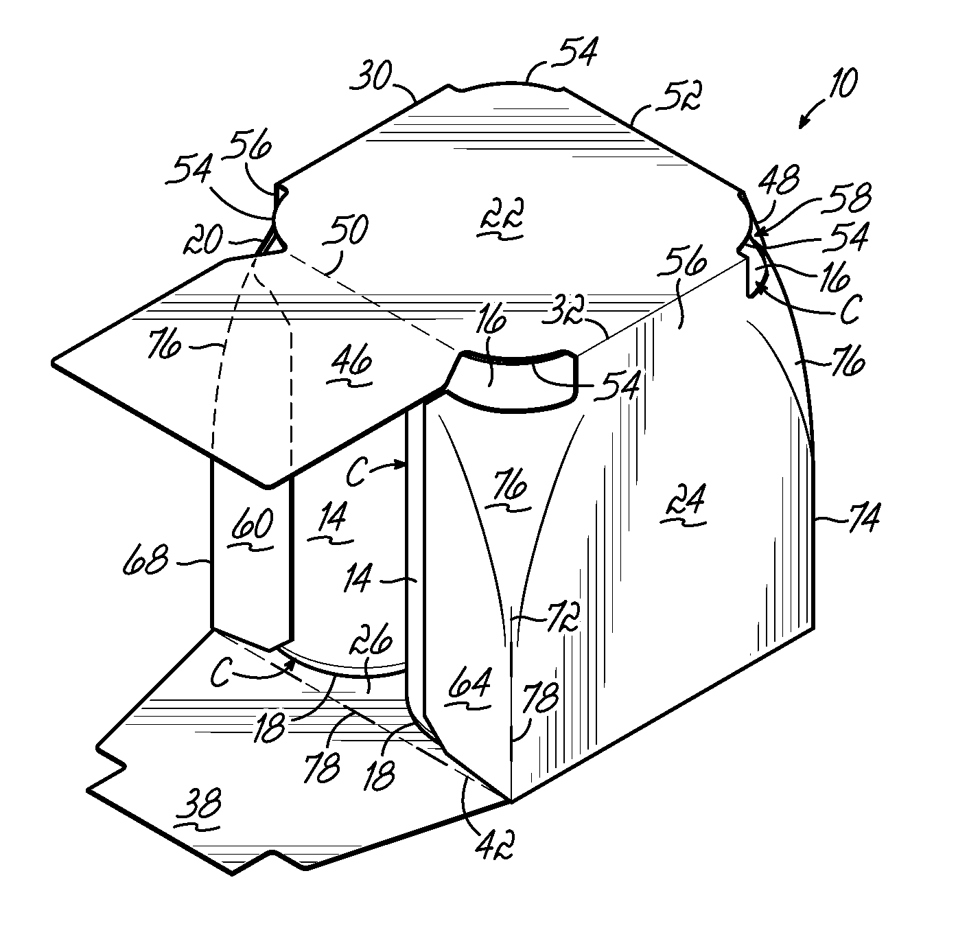
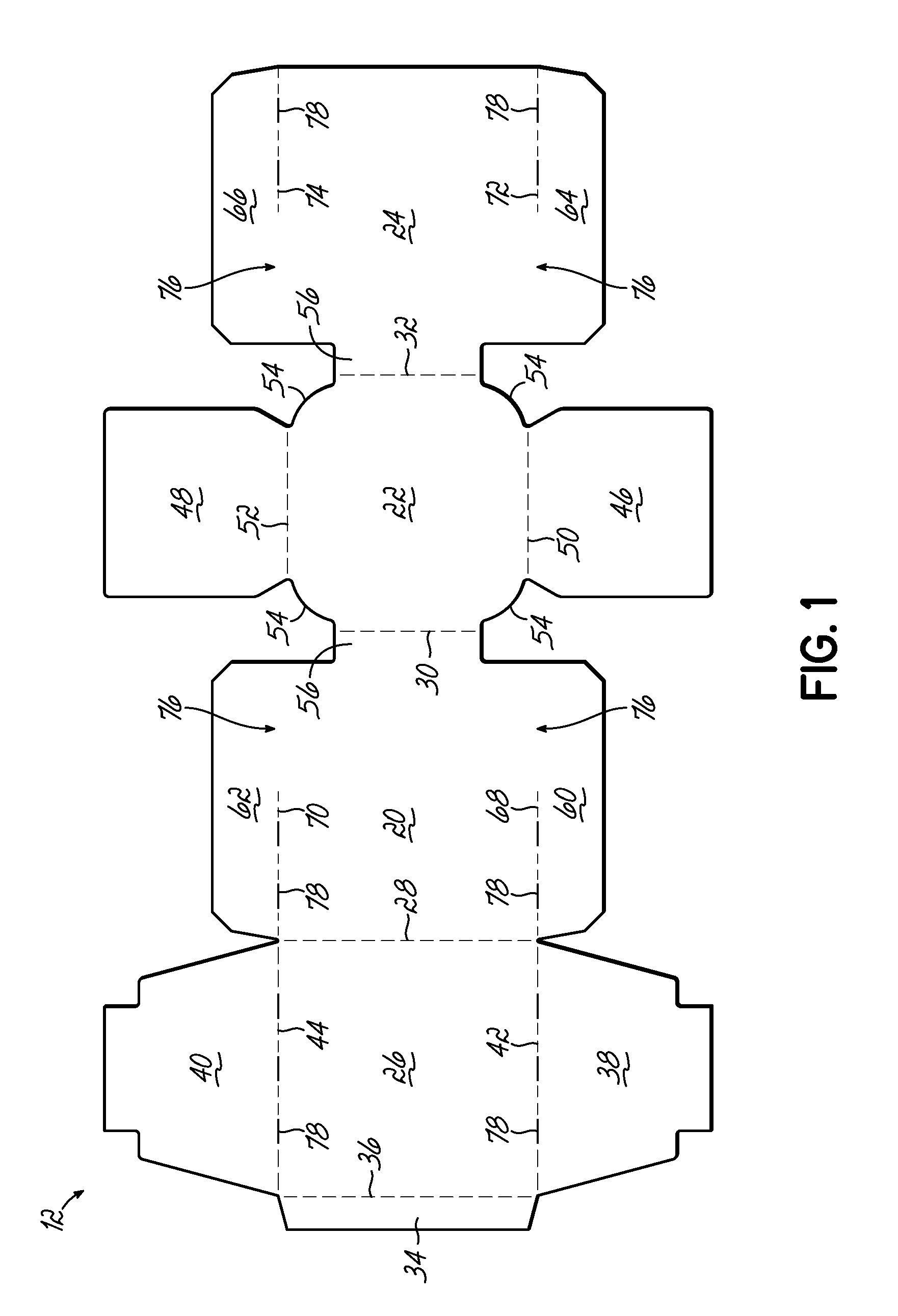
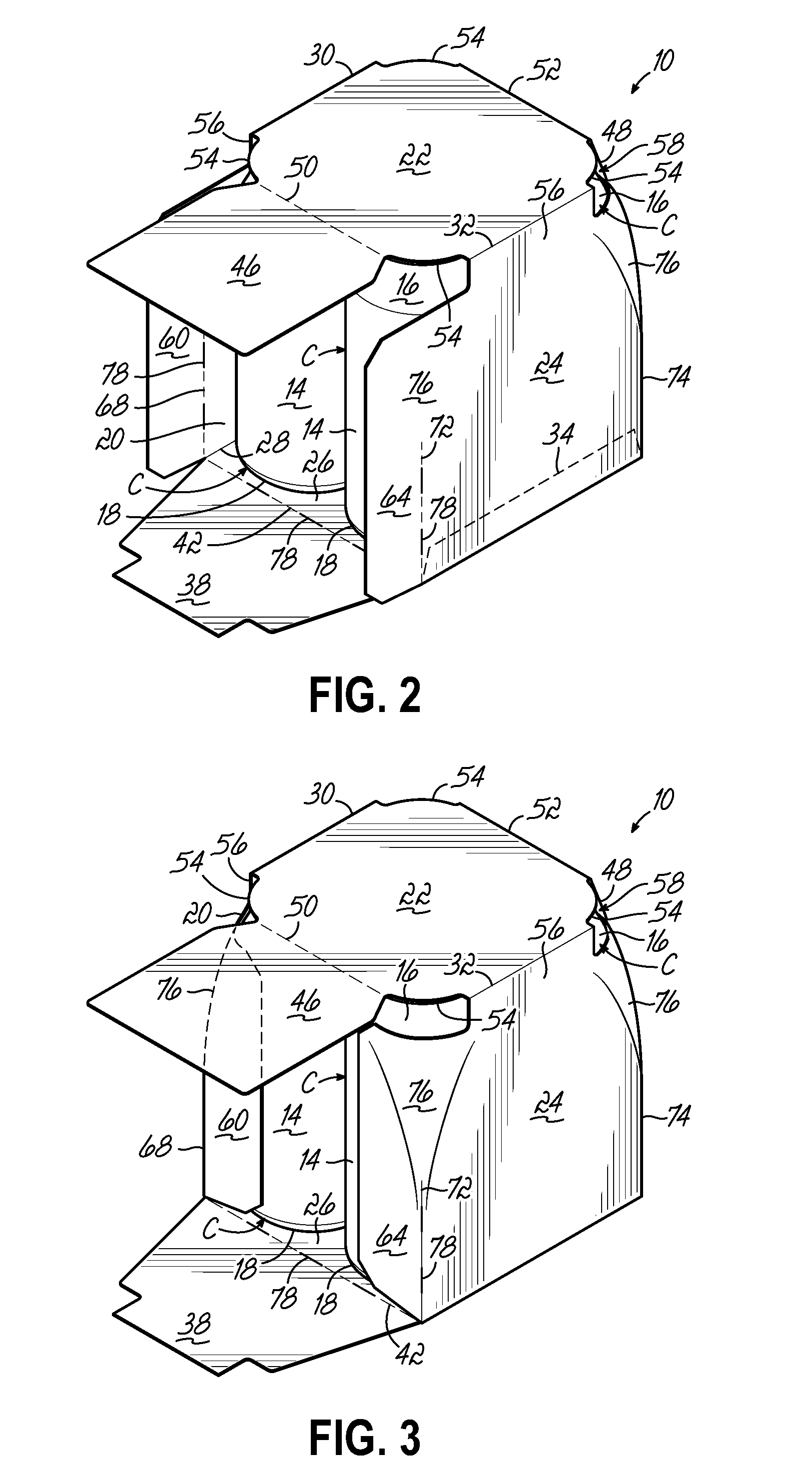
[0024]FIGS. 2-7 illustrate a first embodiment of a carrier 10 according to this invention. FIG. 1 illustrates a blank 12 from which the carrier 10 of FIGS. 2-7 is formed. Cans or containers “C” arranged in a 2×2 array are shown in FIGS. 2-7 as an aid in understanding the invention. However, this invention is not limited to a 2×2 arrangement and is readily used in a 2×3, other arrangement and / or sizes and types of containers. The cans “C” are each similarly oriented and have a cylindrical shape with an arcuate sidewall 14 extending from a top crown 16 of each container 14 to a bottom 18.

[0025]Referring to FIG. 1, the blank 12 includes four primary panels for forming carrier walls including a first side panel 20, a top panel 22, a second side panel 24 and a bottom panel 26 foldably connected one to the next along fold lines 28, 30 and 32. A glue flap 34 is foldably connected to bottom panel 26 along fold line 36.

[0026]Pair of bottom flaps 38, 40 is attached to and extend from opposite...


PUM

PropertyMeasurementUnit
lengthaaaaaaaaaa
shapeaaaaaaaaaa
perimeter profileaaaaaaaaaa

Abstract

A carrier is constructed from paperboard and includes a rounded or non-rectangular top in combination with a non-rounded or rectangular bottom. Dust flaps which extend from the top and bottom of the carrier overlap one another to form a pair of opposing composite side panels. The dust flaps which are attached to the side panels include a crease or fold line adjacent to the bottom of the carrier which only extends partially along the height of the carrier so that the juncture between the side flap and the associated side panel adjacent the top of the carrier does not include a crease or fold line. As such, the side panel and adjacent side flap adjacent the top of the carrier can be tightly wrapped around the arcuate sidewall of the containers within the carrier to thereby provide a neat and tightly packed package configuration.

Description

[0001]This claims priority to U.S. Provisional Application Ser. No. 61 / 648,303, filed May 17, 2012, and hereby incorporated by reference in its entirety.BACKGROUND OF THE INVENTION[0002]The invention relates, generally, to article carriers. More particularly, the invention relates to wrap-around article carriers formed by wrapping a flat carrier blank around a configuration of containers.[0003]Wrap-around article carriers are commonly used to package beverage containers and other articles. Basically, one type of wrap-around article carrier is formed by grouping articles in an arrangement they are desired to be in after packaging to form a product configuration, and then wrapping a flat carrier blank around the product configuration. The blank is tightly drawn about the articles and the ends of the blank are connected to each other. Cutouts are often provided at the upper and / or lower portions of the ends of the carrier to grip the exposed portions of the articles protruding through ...

Claims


Application Information

Patent Timeline
Patent Type & Authority Patents(United States)
IPC IPC(8): B65D71/00B65D1/22
CPCB65D1/22B65D71/36B65D2571/00444B65D2571/0045B65D2571/00524B65D2571/0066B65D2571/00728B65D2571/00845
Inventor BLOCK, STEVEN J.
Owner C W ZUMBIEL
Why Eureka
Try Eureka