Can end

a can end and can end technology, applied in the field of can end, can solve the problems of difficult task, u.s. pat. no. 7 not suitable for large diameter “full aperture", etc., and achieve the effect of convenient opening

Active Publication Date: 2015-04-07
CROWN PACKAGING TECH
View PDF22 Cites 10 Cited by
  • Summary
  • Abstract
  • Description
  • Claims
  • Application Information

AI Technical Summary

Benefits of technology

[0013]Accordingly, there is provided an easily openable can end provided with an end panel, a score line formed in the end panel to define a prearranged opening area, a tab for severing the score line, the tab having a nose and a handle, characterised in that the end panel comprises a moveable portion on which the tab is mounted, the moveable portion adapted to be moveable from a predetermined first state to a predetermined second state to thereby displace the handle of the tab away from the end panel and define a gap between the handle of the tab and the end panel suitable for finger access by a user.
[0015]A consequence of the invention is that it is possible to confine much of the area of the moveable portion so that it is under the tab itself. Therefore, the present invention allows much of the remainder of the end panel to remain generally planar (with the exception perhaps of some strengthening beads or panelling), thereby providing an easier surface on which to print instructions, logos and / or other text / graphics (in contrast to that of U.S. Pat. No. 7,168,586B2).
[0020]Preferably, the tab is mounted on the moveable portion such that in the first state the handle of the tab is biased against the end panel. This may be enabled by the tab including a resiliently formed tongue section, the tab mounted on the moveable portion via the tongue section to bias the handle of the tab against the end panel in the first state. Prior to their attachment to a container body, the can ends would typically be transported—as a stack, one can end upon another—with the moveable portion in this first state. Consequently, having the handle of the tab biased against the end panel has the advantage of resisting foreign objects or adjacent can ends becoming stuck or locked under the handle of the tab.
[0023]In an especially preferred embodiment, the moveable portion is provided on a platform elevated relative to the remainder of the end panel such that in the first state, the lowermost point of the moveable portion does not extend below the lowermost plane of the can end, thereby enhancing stackability of the can end.
[0026]Conveniently, the moveable portion is formed as a generally upwardly projecting convex protrusion and a generally downwardly projecting concave protrusion in first and second states respectively. Preferably, the tab is mounted on an inclined region of the moveable portion such that when occupying the first “convex” state, the tab handle is inclined towards the end panel, with transformation to the second “concave” state inclining the tab handle upwardly away from the end panel to thereby provide the gap between the handle of the tab and the end panel suitable for finger access by a user. The inclination referred to is measured relative to the horizontal plane generally defined by the can end. This aspect of the invention takes advantage of the natural curvature that a convex / concave protrusion possesses and the full or partial reversal in inclination that it undergoes when changing between convex and concave states. Mounting the tab on the inclined region of the moveable portion, and the reversal in inclination that occurs on transformation from first “convex” to second “concave” states provides an efficient mechanism for displacing the tab and providing finger access under the tab. Summarising, mounting the tab in this manner means that for a tab of a given length, the invention requires a moveable portion of a smaller area than that of the finger well of U.S. Pat. No. 7,168,586B2 to provide the same gap under the handle of the tab.
[0032]For either of mechanisms 1 or 2, the convex / concave profile of moveable portion referred to above can be achieved by pressing or stamping the end panel of the can end to thereby plastically deform the material of the can end to form the moveable portion with the convex / concave profile. In this way, the moveable portion may form an integral part of the end panel of the can end. The advantage of such a convex / concave profile is that it provides inherent bistability. This inherent bistability is provided because the distance measured along the convex / concave surface of the moveable portion from one point to another is greater than the linear distance between these two points. Consequently, the moveable portion has to be “squeezed” through a smaller gap in order to revert to and fro between first and second states, therefore requiring a force to induce this change.

Problems solved by technology

However, this presents a problem for a consumer wishing to open the can because they must first prise the handle of the tab away from the surface of the end panel in order to lift the tab to rupture the score line.
The lack of clearance between the tab handle and the end panel makes this a difficult task, especially for those with weak hands.
However, there are several problems with the protrusion shown and described in U.S. Pat. No. 7,168,586B2:The invention of U.S. Pat. No. 7,168,586B2 is not suitable for large diameter “full-aperture” can ends.
These two requirements increasingly conflict with each other for larger diameter can ends.

Method used


Image

  • Can end
  • Can end
  • Can end

Examples


Embodiment Construction

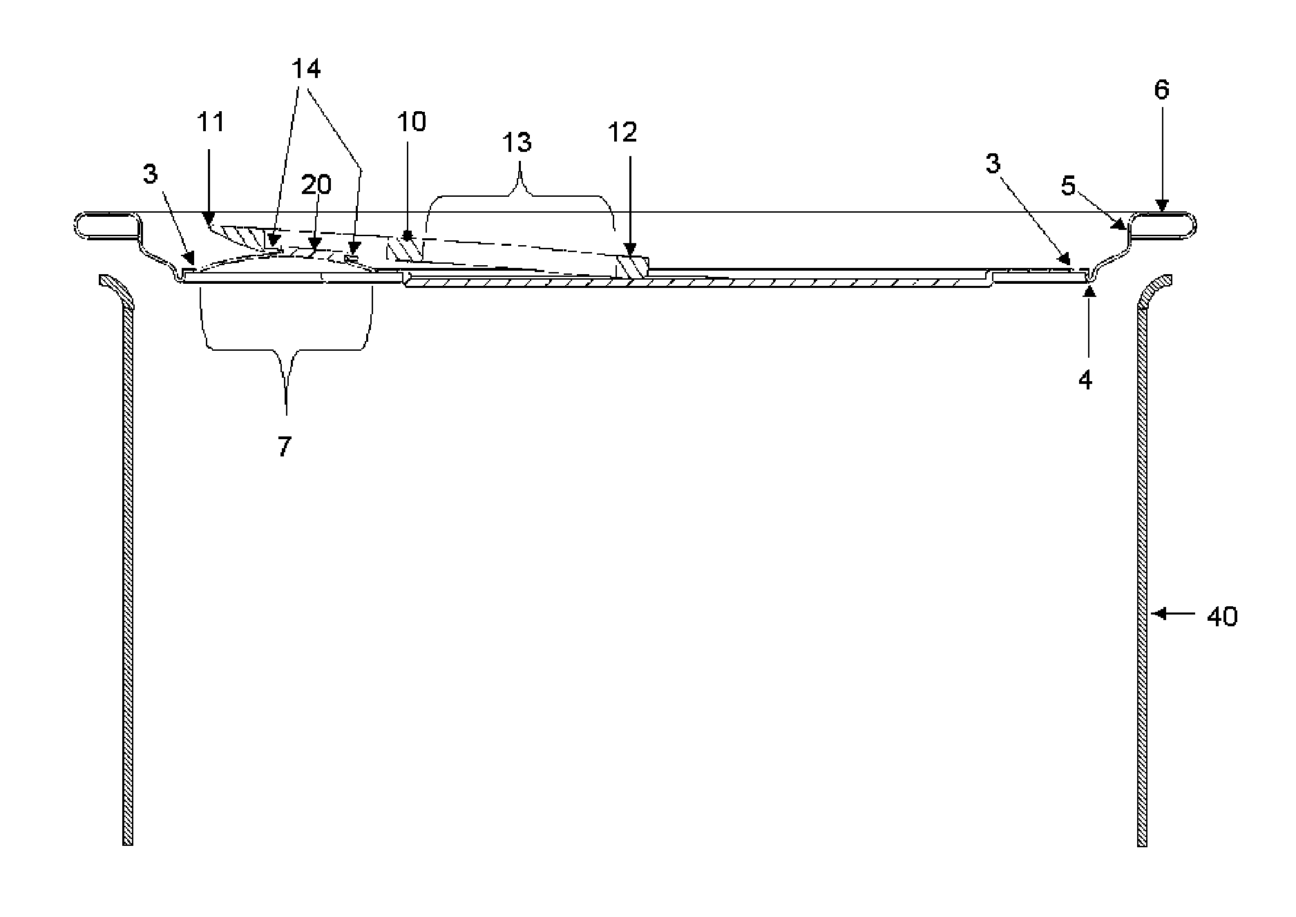
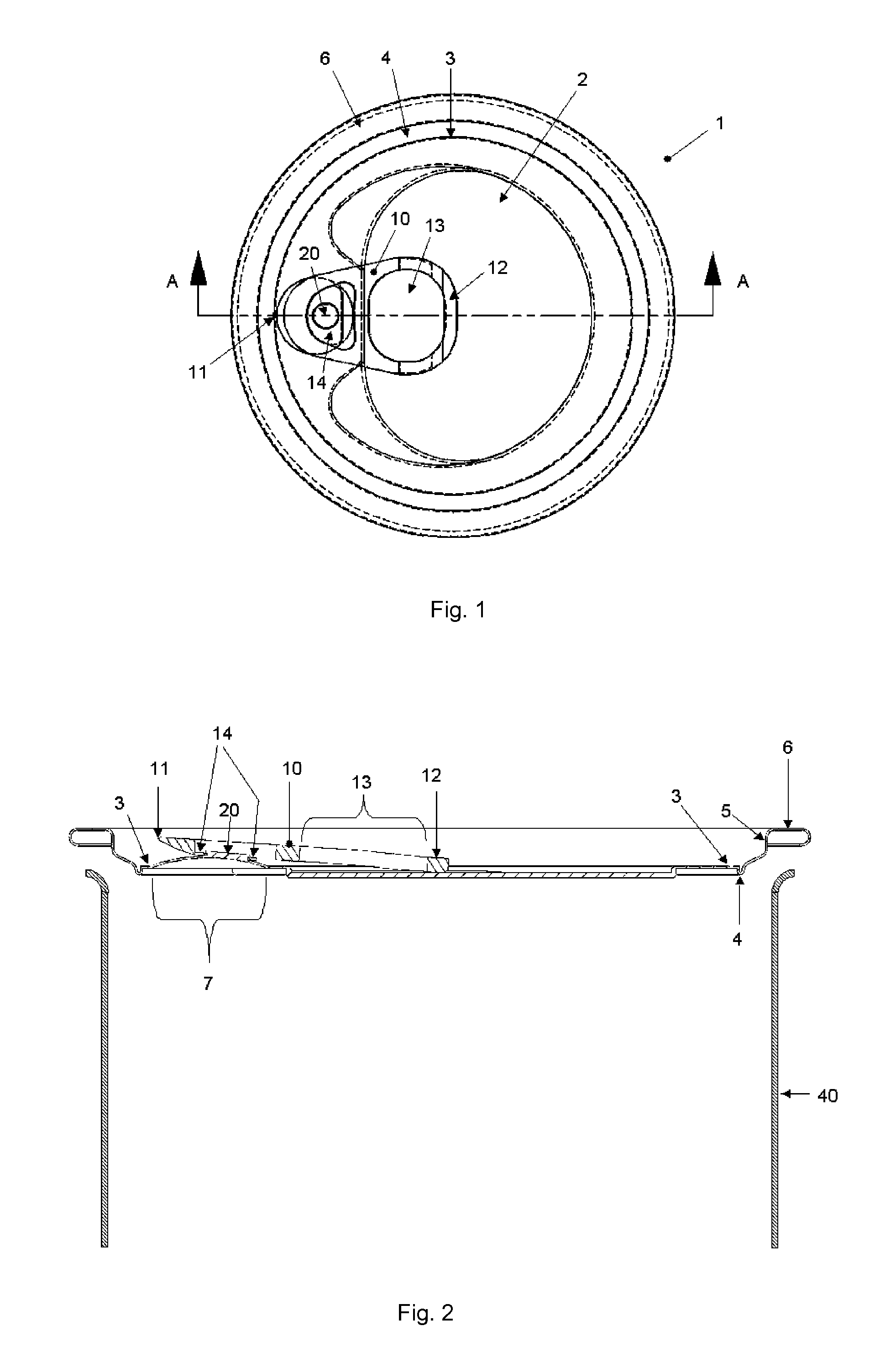
[0043]A first embodiment of the invention is shown in FIGS. 1 to 3 and corresponds generally to “Mechanism 1” described above.

[0044]Can end 1 includes an end panel 2 provided with a score line 3 (see FIG. 1). The score line 3 extends continuously about the periphery of the end panel 2 to define a prearranged opening area (in this case, a “full-aperture”). In the embodiment illustrated, the whole of the end panel 2 inwards of the score line is removable from the can end 1. However, in an alternative embodiment, the score line 3 may not be continuous and the portion of the end panel 2 inwards of the score line 3 is retained by the can end; for example, as found on many beverage can ends.

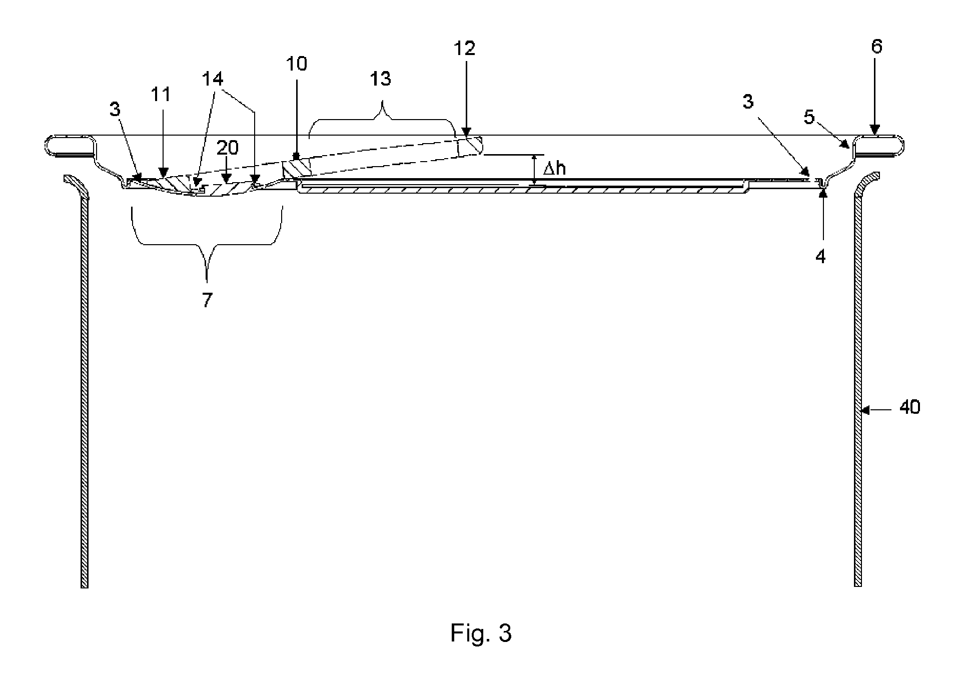
[0045]Returning to the embodiment of FIGS. 1 to 3, the end panel 2 includes a countersink 4 located radially outwards of the score line 3 (see FIGS. 2 & 3). A chuck wall 5 extends first upwardly from the countersink 4, and then outwardly to define seaming panel 6 (see FIGS. 2 & 3). The seaming panel 6 ...


PUM


Abstract

The invention is an easily openable (1) can end which provides an improved way of providing finger access under the tab for a consumer. A can end is disclosed having an end pane (2)1, the end panel including a moveable portion (7) on which the tab is mounted. Finger access is provided by the moveable portion being moveable from a predetermined first state to a predetermined second state to thereby displace the handle of the tab away from the end panel and define a gap between the handle of the tab and the end panel suitable for finger access by a user.

Description

CROSS-REFERENCE TO RELATED APPLICATIONS[0001]This application is the National Stage of International Application No. PCT / EP2010 / 055366, filed Apr. 22, 2010, which claims the benefit of EP application number 09158566.1, filed Apr. 23, 2009, the disclosures of which are incorporated herein by reference in their entirety.TECHNICAL FIELD[0002]This invention relates to an easy open can end with an improved means of opening. The invention is particularly suitable for use on metal packaging for food and beverage products. Variants of the invention are disclosed which are particularly suitable for containers subject to either negative pressure or positive internal pressure.BACKGROUND ART[0003]Easy-open can ends are well known in the field of can manufacture—for example, that disclosed in FIGS. 4 & 5 of U.S. Pat. No. 5,413,241 (YEH HSI-SHOU) 9 May 1995. The can end disclosed is provided with an end panel having a score line defining a prearranged opening area to provide a “full-aperture” end...

Claims


Application Information

Patent Timeline
Patent Type & Authority Patents(United States)
IPC IPC(8): B65D17/34B65D17/00B65D79/00
CPCB65D17/165B65D17/163B65D79/005B65D2517/0013B65D2517/007B65D2517/0076B65D2517/0089B65D17/4011B65D17/4012B65D79/008
Inventor WILLIAMS, ANDREW RICHARDKEANE, BRENDANFIELDS, BRIAN
Owner CROWN PACKAGING TECH
Why Eureka
Try Eureka