Plastic clip

a plastic clip and clip body technology, applied in the field of plastic clips, can solve the problems of unstable assembly state of the clip main body relative to the clip boss, flowage and noise of the clip main body, etc., and achieve the effects of improving durability and merchantability, improving assembly properties, and easy and firmly assembled

Active Publication Date: 2015-04-14
NIFCO KOREA
View PDF25 Cites 4 Cited by
  • Summary
  • Abstract
  • Description
  • Claims
  • Application Information

AI Technical Summary

Benefits of technology

[0011]In the plastic clip of the present invention, the clip main body is easily and firmly assembled to the clip boss integrally formed in the fixed panel, so that as well as improving an assembly property of the clip main body, a flowage or noise of the clip main body due to an external impact in a usage process can be significantly reduced, and in a process of assembling the fixed panel to the combination panel or disassembling the fixed panel from the combination panel, a breakage of the clip main body can be prevented so as to obtain an effect of significantly improving a durability and merchantability of the plastic clip.

Problems solved by technology

Also, in a conventional structure, an assembly state of the clip main body relative to the clip boss is unstable, and there is a problem that a flowage and noise of the clip main body due to an external impact in a usage process occur.

Method used


Image

  • Plastic clip
  • Plastic clip
  • Plastic clip

Examples


Embodiment Construction

[0018]Hereinafter, specific description of the present invention for obtaining the aforementioned object will be explained in detail based on attached drawings.

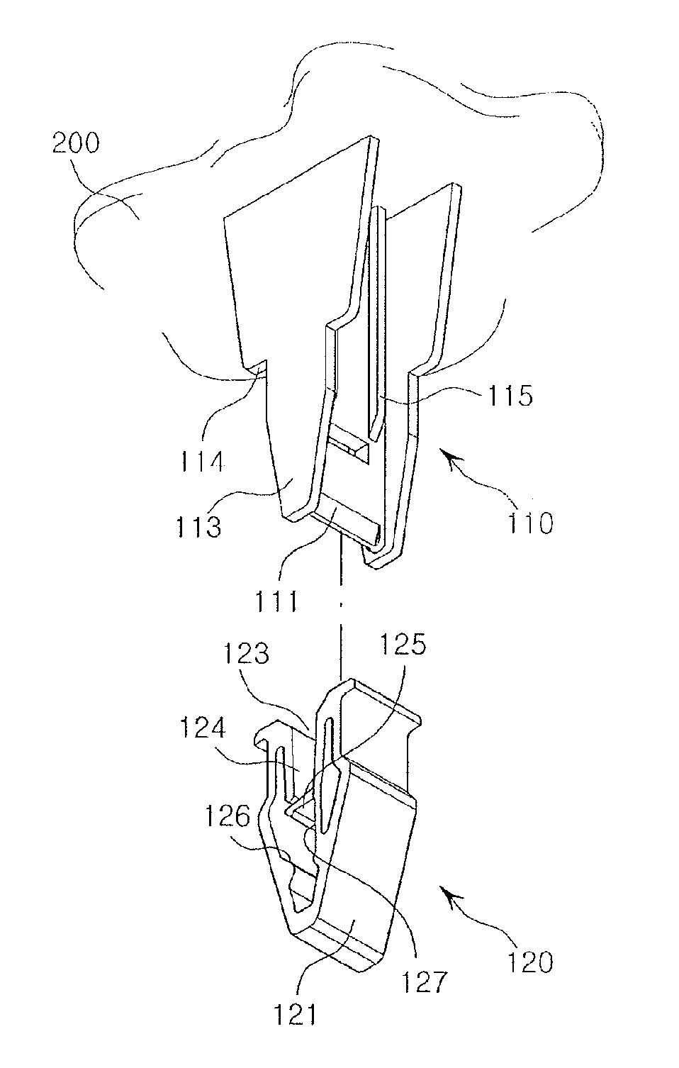
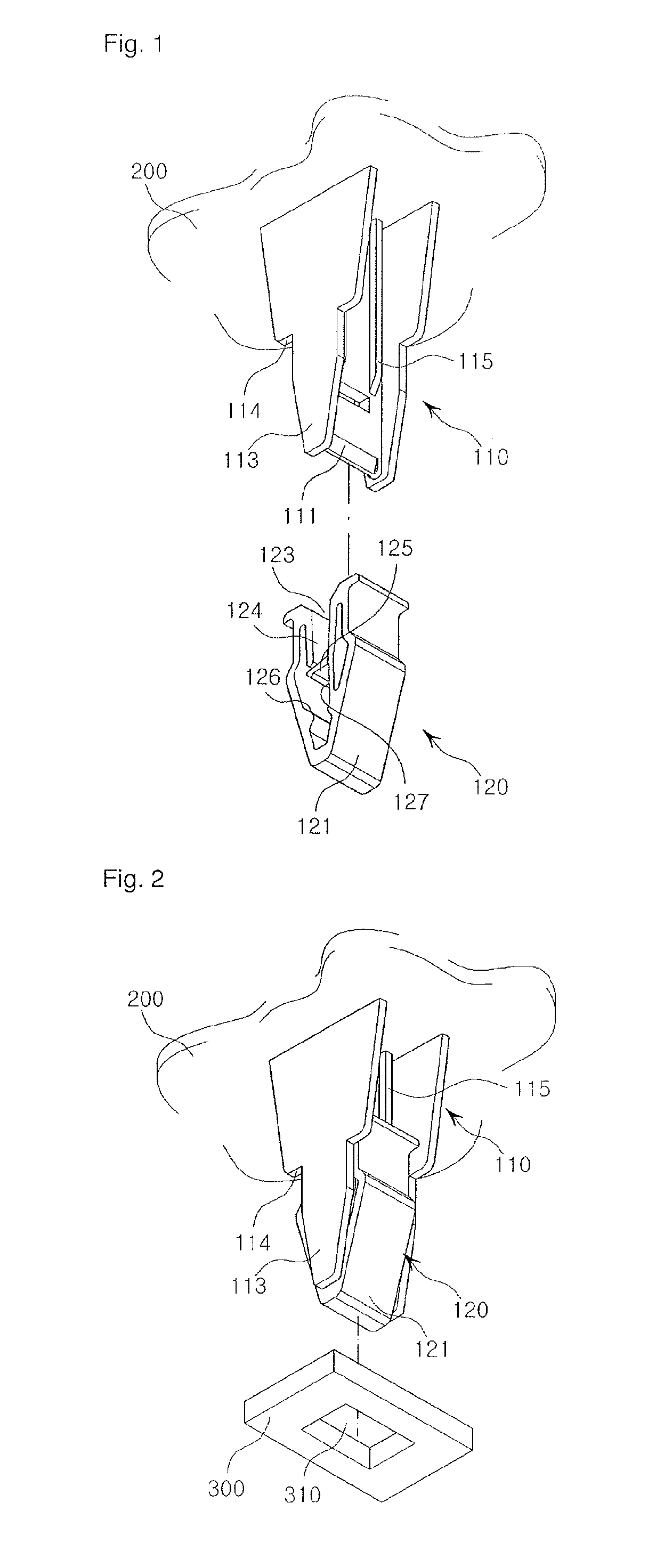
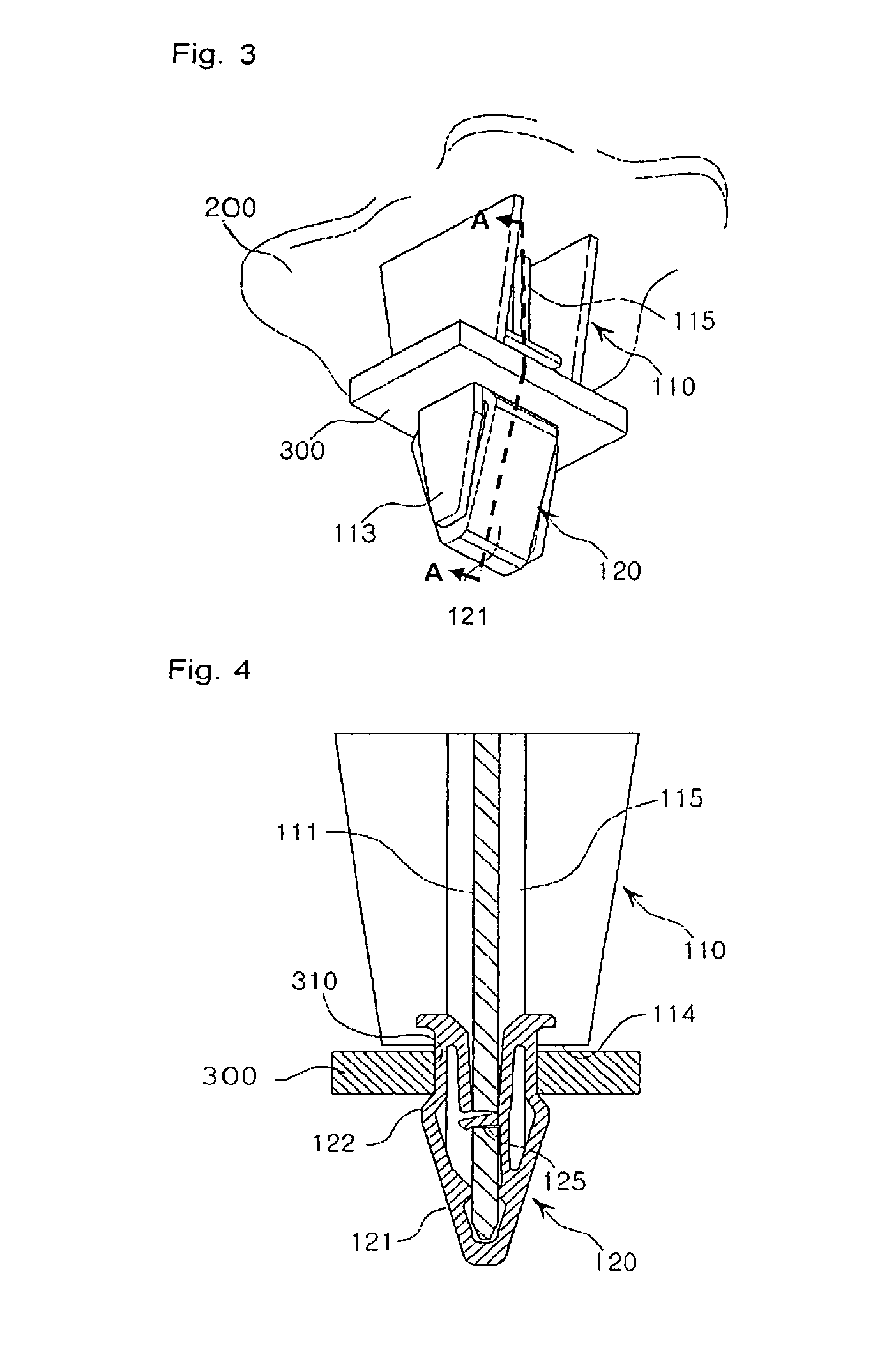
[0019]FIG. 1 is an exploded perspective view of a plastic clip according to one embodiment of the present invention; FIG. 2 is a perspective view showing a state before a combination panel is combined with the plastic clip according to one embodiment of the present invention; and FIG. 3 is a perspective view showing a state after the combination panel is combined with the plastic clip according to one embodiment of the present invention.

[0020]Also, FIG. 4 is a longitudinal cross-sectional view showing the state after the combination panel is combined with the plastic clip according to one embodiment of the present invention; and FIG. 5 is a substantial enlarged view of FIG. 4.

[0021]As shown in FIG. 1 to FIG. 5, a plastic clip 100 of the present invention comprises a clip boss 110 integrally formed in a fixed panel 200; and a ...


PUM


Abstract

A plastic clip of the present invention includes a clip boss integrally formed in a fixed panel; and a clip main body detachably assembled to the clip boss. The clip boss includes fitting portions provided in two lower side portions of a vertical plate provided with a fitting hole; and locking projections provided in front and back upper ends of the fitting portions. The clip main body includes an inverted triangular input portion provided in a lower end portion; a locking projection provided in an upper end portion of the input portion; a clip-boss input guide hole provided in the center of an upper end; a clip-boss input guide portion provided in the center of an internal upper portion and connected to the clip-boss input guide hole; and an elastic fitting piece provided in a lower end of the clip-boss input guide portion.

Description

RELATED APPLICATIONS[0001]The present application is National Phase of International Application No. PCT / KR2012 / 001139 filed Feb. 15, 2012, and claims priority from Korean Application No. 10-2011-0014045, filed Feb. 17, 2011.FIELD OF TECHNOLOGY[0002]The present invention relates to a plastic clip, more specifically, a plastic clip in which a clip main body is combined with a clip boss integrally formed in a fixed panel.BACKGROUND ART[0003]Generally, various interior materials beginning with a fascia board (FACIA) inside an automobile are configured wherein a combination panel is assembled to the fixed panel, and when the combination panel is assembled to the fixed panel in this manner, there are many examples using a plastic clip composed of the clip boss integrally formed in the fixed panel, and the clip main body detachably assembled to the clip boss.[0004]However, conventionally, in the plastic clip composed of the clip boss integrally formed in the fixed panel, and the clip main...

Claims


Application Information

Patent Timeline
Patent Type & Authority Patents(United States)
IPC IPC(8): F16B2/22B60R13/02F16B5/06F16B21/07F16B21/12
CPCF16B2/22F16B21/075B60R13/0206F16B5/0657Y10T24/44752F16B5/065F16B21/12Y10T24/30Y10T24/309B60R16/00B60R16/02
Inventor CHOI, YOUN YOUNG
Owner NIFCO KOREA
Why Eureka
Try Eureka