Article transport facility with intermediate transfer device

a technology of transfer device and transport facility, which is applied in the direction of transportation and packaging, conveying, pile separation, etc., can solve the problems of traffic congestion of ceiling transport vehicles on the travel rail, and achieve the effect of reducing transporting load and increasing transfer demand

Active Publication Date: 2015-04-14
DAIFUKU CO LTD
View PDF18 Cites 28 Cited by
  • Summary
  • Abstract
  • Description
  • Claims
  • Application Information

AI Technical Summary

Benefits of technology

[0014]With this characteristic configuration, the intermediate rack is located at a position that is different from the article delivering and receiving portion in the travel direction of the ceiling transport vehicle: the stop position for the delivering and receiving portions is set at a position that is in vertical alignment with the article delivering and receiving portion: and, the stop position for the intermediate rack is set at a position that is in vertical alignment with the intermediate rack. Thus, when the ceiling transport vehicle transfers an article to the article delivering and receiving portion or the intermediate rack, the ceiling transport vehicle, the intermediate transfer device, and the article delivering and receiving portion are aligned with one another in the vertical direction as seen along the travel direction of the ceiling transport vehicle. Thus, the position of the ceiling transport vehicle coincides with the position of the article delivering and receiving portion in the lateral direction as seen along the travel direction so that the lateral width of the space taken up by the ceiling transport vehicle and the article delivering and receiving portion can be made compact. Therefore, the space above the article delivering and receiving portion can be utilized efficiently over the entire vertical range, which is advantageous in respect of securing installation space.
[0036]Further, since the intermediate transfer device can move from the transfer target group of the article processing device which it is assigned to the transfer target groups of other article processing devices, when an article on which a processing by a certain article processing device has been completed is transported to a transfer target group of another article processing device, for example, the article can be transported to the transfer target group of another article processing device by the intermediate transfer device that is assigned to the transfer target group of the article processing device which completed the processing instead of transporting the article in question with the ceiling transport vehicle. This can reduce the transporting load of a ceiling transport vehicle.

Problems solved by technology

Since, among other reasons, article handling throughput of an article delivering and receiving portion increases when a number of article transfer operations to or from the article delivering and receiving portion are performed in a row by ceiling transport vehicles, the ceiling transport vehicles that need to transfer articles to or from the article delivering and receiving portion end up forming a waiting line, which may result in a traffic congestion of the ceiling transport vehicles on the travel rail.

Method used


Image

  • Article transport facility with intermediate transfer device
  • Article transport facility with intermediate transfer device
  • Article transport facility with intermediate transfer device

Examples


first embodiment

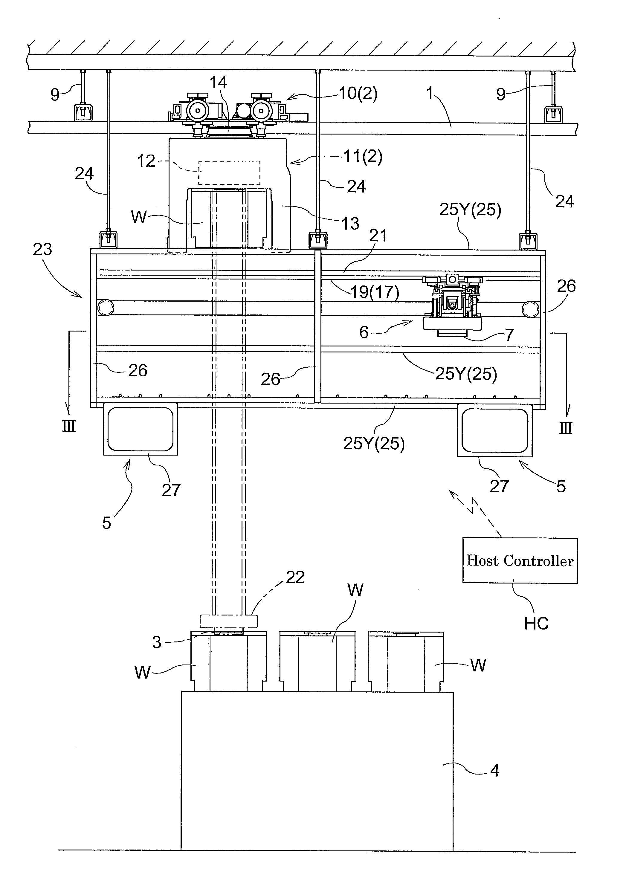
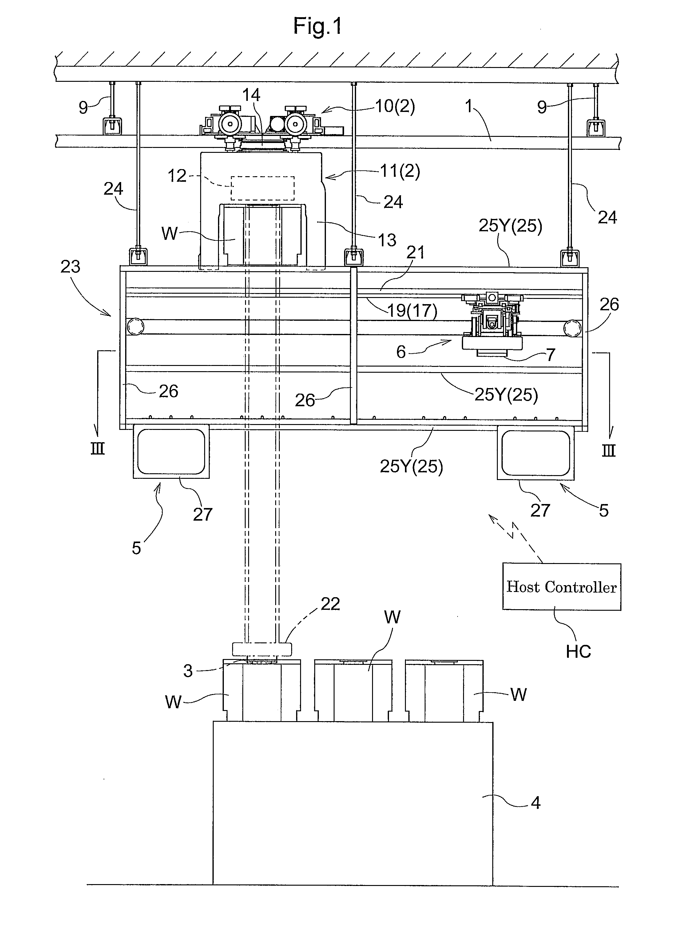
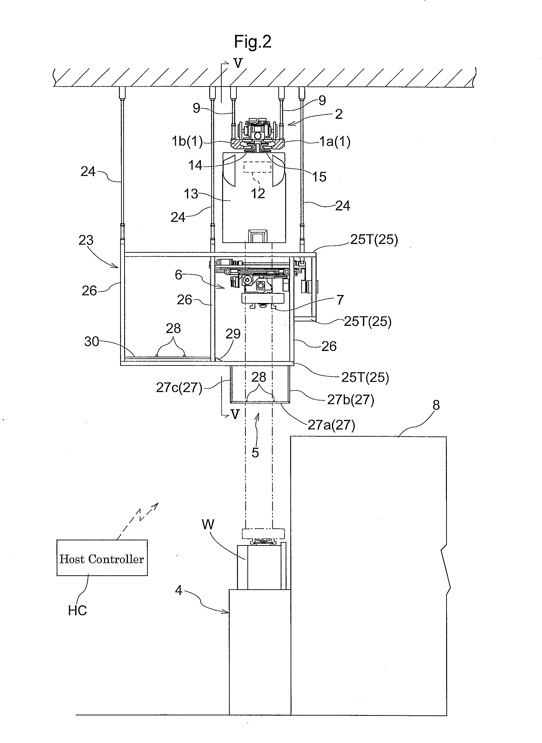
[0051]The first embodiment of the article transport facility in accordance with the present invention is described with reference to the drawings. As shown in FIGS. 1 and 2, the article transport facility includes one or more ceiling transport vehicle or vehicles 2 that can travel along a travel rail 1 disposed on the ceiling side. The ceiling transport vehicle 2 includes a grip portion 3 for supporting an article W such that the grip portion can be raised and lowered or moved vertically, and is configured to be able to transfer an article W to or from a station 4 by vertically moving the grip portion 3 with the ceiling transport vehicle 2 stopped at a stop position Q1 (see Q1a, Q1b, or, Q1c in FIG. 4) for the delivering and receiving portion, set at a position which is in vertical alignment, or overlaps in the vertical direction, with the station 4, which functions as an article delivering and receiving portion provided on the floor side. While the travel rail 1 includes straight s...

second embodiment

[0087]The second embodiment of the article transport facility in accordance with the present invention is described next. The present embodiment has the same configuration as the first embodiment except for the configuration of the buffer frame 23 in the first embodiment and also for the moving range, of the intermediate transfer device 6, which is different. Therefore, the ceiling transport vehicle 2 or the intermediate transfer device 6 will not be described in detail below. And it is to be understood that features that are not specifically described are identical to those in the first embodiment.

[0088]As shown in FIG. 10, two article processing devices 8 are arranged next to each other in the travel direction of the ceiling transport vehicle 2 in the present embodiment. The travel direction of the ceiling transport vehicle 2 is directed from left to right on the paper in FIG. 10. The article processing device 8 located on the left-hand side on the paper in FIG. 10 (upstream side ...

third embodiment

[0101]The third embodiment of the article transport facility in accordance with the present invention is described next. The present embodiment differs from the second embodiment described above in that the buffer frame 55 is provided with two intermediate transfer devices.

[0102]As shown in FIGS. 13 and 14, there are provided a first intermediate transfer device 6a which is assigned to, or in charge of, article transfers to or from the transfer target group G1 for the first processing device 8a, and a second intermediate transfer device 6b which is assigned to, or in charge of, article transfers to or from the transfer target group G2 for the second processing device 8b. Each of the first intermediate transfer device 6a and the second intermediate transfer device 6b is supported by a pair of lower guide rails 18, 19 that function as the guiding support 17 provided in the buffer frame 55 such that its movement in the travel direction is guided by the lower guide rails 18, 19. As such...


PUM


Abstract

An intermediate transfer device is located upwardly of an article delivering and receiving portion and downwardly of a ceiling transport vehicle. A transfer device grip is provided such that the intermediate transfer device is in vertical alignment with the ceiling transport vehicle and the article delivering and receiving portion and is capable of traveling, while guided and supported by a guiding support, to and among a transfer position for the delivering and receiving portion, a transfer position for the intermediate rack, a transfer-time retracted position, and a temporary-storage-time retracted. The guiding support is configured to form a space through which the grip portion and an article can pass in the vertical direction when the ceiling transport vehicle transfers the article.

Description

FIELD OF THE INVENTION[0001]The present invention relates to an article transport facility comprising a ceiling transport vehicle that is capable of traveling along a travel rail arranged on a ceiling side, that includes a grip portion for supporting an article such that the grip portion can be vertically moved, and that is capable of transferring an article to or from an article delivering and receiving portion provided on a floor side; and an intermediate rack for temporarily storing an article to be transferred to the article delivering and receiving portion, the intermediate rack being located upwardly of the article delivering and receiving portion and downwardly of the ceiling transport vehicle.BACKGROUND OF THE INVENTION[0002]Since, among other reasons, article handling throughput of an article delivering and receiving portion increases when a number of article transfer operations to or from the article delivering and receiving portion are performed in a row by ceiling transp...

Claims


Application Information

Patent Timeline
Patent Type & Authority Patents(United States)
IPC IPC(8): B65G1/00B65G1/04B65G1/06B66C19/00H01L21/677H01L21/687
CPCB65G1/065B65G1/0464H01L21/67733H01L21/67736H01L21/67769H01L21/68707B66C19/00B65G2201/0297B65G1/0457H01L21/6773
Inventor KINUGAWA, TOMOTAKASHIBATA, SUGURUOGAWA, DAISUKE
Owner DAIFUKU CO LTD
Why Eureka
Try Eureka