Charge pump device

a technology of a pump device and a driving capability, which is applied in the direction of process and machine control, instruments, and apparatus without intermediate ac conversion, etc., can solve the problems of large periodic output ripples, unstable output voltage, and noise in the audio frequency band of the charge pump, so as to avoid audio noise and enhance stability

Active Publication Date: 2015-04-14
NOVATEK MICROELECTRONICS CORP
View PDF8 Cites 5 Cited by
  • Summary
  • Abstract
  • Description
  • Claims
  • Application Information

AI Technical Summary

Benefits of technology

[0017]A charge pump device is disclosed, capable of avoiding audio noise and enhancing stability.

Problems solved by technology

Under the structure utilizing the operational amplifier for performing controlling, the output voltage has smaller output ripples but may be unstable under different loadings and different external components.
Although the output voltage is stable under the structure utilizing the comparator for controlling, the output voltage has greater periodic output ripples and may have noise in audio frequency band under certain loadings.
However, since the output of the charge pump device 10 has a pole equals 1 / (2π×CS1×loading resistance), the pole varies due to different external loadings and different capacitances of output capacitor CS1, causing the charge pump 10 to be unstable under certain circumstances.
Thus, the comparator structure may generate audio noise which can be heard by human ear (20 Hz-20 kHz) under certain external loadings.
Therefore, although the charge pump device 20 controlled by the comparator does not cause problem of stability, the charge pump device 20 has greater output ripple which results in the audio noise under certain external loadings.

Method used


Image

  • Charge pump device
  • Charge pump device
  • Charge pump device

Examples


Embodiment Construction

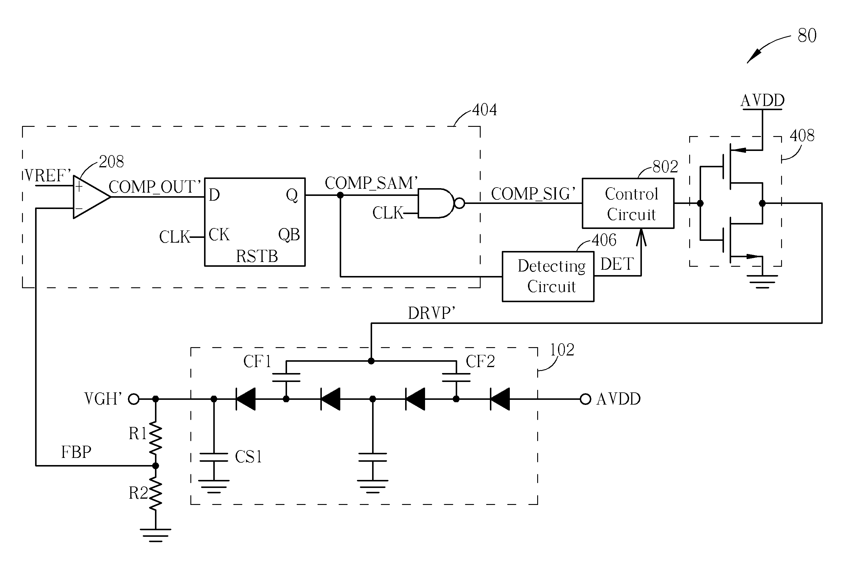
[0032]Please refer to FIG. 4A, which is a schematic diagram of a charge pump device 40 according an embodiment. The charge pump device 40 is partially similar to the charge pump device 20. Thus, the components and the signals with similar functions are denoted by the same symbols. As shown in FIG. 4A, the charge pump device 40 comprises a charge pump circuit 402, a comparing circuit 404, a detecting circuit 406 and a driving stage 408. Simply speaking, the charge pump circuit 402 generates an output voltage VGH′ either directly or indirectly according to a driving signal DRVP′. The comparing circuit 404 generates a comparison result COMP either directly or indirectly according to the output voltage VGH′ and a reference voltage VREF′. The detecting circuit 406 detects a frequency range of the ripple of the output voltage VGH′, and generates a detection result DET. The driving stage 408 generates the driving signal DRVP′ and adjusts a driving capability corresponding to the driving si...


PUM


Abstract

A charge pump device includes a charge pump circuit, for generating an output voltage according to a driving signal, a comparing circuit, for generating a comparison result according to the output voltage and a reference voltage, a detecting circuit, for detecting a frequency range of a ripple of the output voltage according to the comparison result and generating a detection result, and a driving stage, for generating the driving signal according to the comparison result, and adjusting a driving capability corresponding to the driving signal according to the detection result.

Description

BACKGROUND OF THE INVENTION[0001]1. Field of the Invention[0002]The present invention relates to a charge pump device and driving capability adjustment method thereof, and more particularly, to a charge pump device and driving capability adjustment method thereof capable of adjusting an output driving capability according to loading status while balancing both output ripple and loading affording capability.[0003]2. Description of the Prior Art[0004]Generally speaking, a charge pump device can be utilized for providing a stable output voltage to different loadings. In the prior art, the charge pump device is controlled by an operational amplifier or by a comparator. Under the structure utilizing the operational amplifier for performing controlling, the output voltage has smaller output ripples but may be unstable under different loadings and different external components. Although the output voltage is stable under the structure utilizing the comparator for controlling, the output vo...

Claims


Application Information

Patent Timeline
Patent Type & Authority Patents(United States)
IPC IPC(8): G05F1/10H02M3/07
CPCH02M3/07
Inventor CHIU, HSIANG-YI
Owner NOVATEK MICROELECTRONICS CORP
Why Eureka
Try Eureka