Data signal receiver and method of calibrating a data signal receiver

a data signal and receiver technology, applied in the field can solve the problems of inconvenient calibration of data signal receivers, inability to accurately calibrate data signal receivers, and difficulty in reading data eye training process

Active Publication Date: 2015-04-14
ARM LTD
View PDF15 Cites 17 Cited by
  • Summary
  • Abstract
  • Description
  • Claims
  • Application Information

AI Technical Summary

Benefits of technology

[0014]Accordingly, by this technique the centres of the read eyes for each bit of the multi-bit data signal are aligned with one another, advantageously providing an overall improvement in the setup and hold time margins for each bit of the read eyes over prior art approach in which the read eye starts for each bit are arranged to align with one another.
[0026]The incrementation of the timing offset may advantageously be performed as a two stage process, in which coarse increments are made in the first stage and fine increments are made in the second stage. This enables the start of the predetermined pattern to be more quickly and efficiently determined. Coarse (i.e. greater) increments are used in the first stage to shift the received predetermined data pattern more quickly relative to the predetermined data pattern portion, and once a match has been found in this first stage the timing offset is stepped back from the latest coarse increment at which the match was found to begin the second stage in which fine (i.e. smaller) increments are made to determine the precise start position of the predetermined data pattern.
[0035]In some embodiments said bit timing delay applied to each bit of said multi-bit data signal is initially set to a minimum value, said minimum value selected such that said sample of said predetermined data pattern received in said receiving step does not match said predetermined data pattern portion. Intentionally setting the bit timing delay applied to each bit of the multi-bit data signal in this way means that the comparison between the sample of the predetermined data pattern received and predetermined data pattern portion will initially fail, and only after further iterations of the process will samples start to match, meaning that the start of the data read eye can be reliably identified and a loss of eye opening is avoided.
[0042]Whilst it is preferable, for the reasons discussed above, for the read eyes of the multi-bit data signal to be aligned such that their respective centres are co-aligned and for the data strobe signal to be aligned with the same timing, it has further been recognised that situations may arise in which the bit timing delay required for at least one of the bits of the multi-bit data signal is too great for this to be possible. In such a situation, this embodiment provides that an alternative method for calibrating the system may be employed, namely one in which the starts of the respective data eyes are aligned. The data strobe signal is then aligned with a position half-way between these aligned starts and the earliest end of any of the data eyes of the multi-bit data signal i.e. mid-way along the shortest eye amongst the data eyes. This technique is referred to herein as the “minimal eye” mode and provides a useful fall-back position whereby calibration of the read data eye is nonetheless possible, despite not being possible to achieve according to the preferred method.

Problems solved by technology

However, as differential data rates increase, for example at the DDR data rates above 1600 Mb / s in a DDR3 system, the read data eye training process becomes particularly difficult, because of the presence of system jitter, PCB trace skew and DRAM uncertainty which render known automated self-calibration systems unreliable.
In high frequency regimes (for example operating at data rates of 2133 Mb / s, where the ideal data eye has an opening of only 468 ps), typical system jitter, PCB trace skew and DRAM uncertainty are such that the above-mentioned technique of simply seeking to set the DQS in the centre of the DQ bus is not reliable.

Method used


Image

  • Data signal receiver and method of calibrating a data signal receiver
  • Data signal receiver and method of calibrating a data signal receiver
  • Data signal receiver and method of calibrating a data signal receiver

Examples


Embodiment Construction

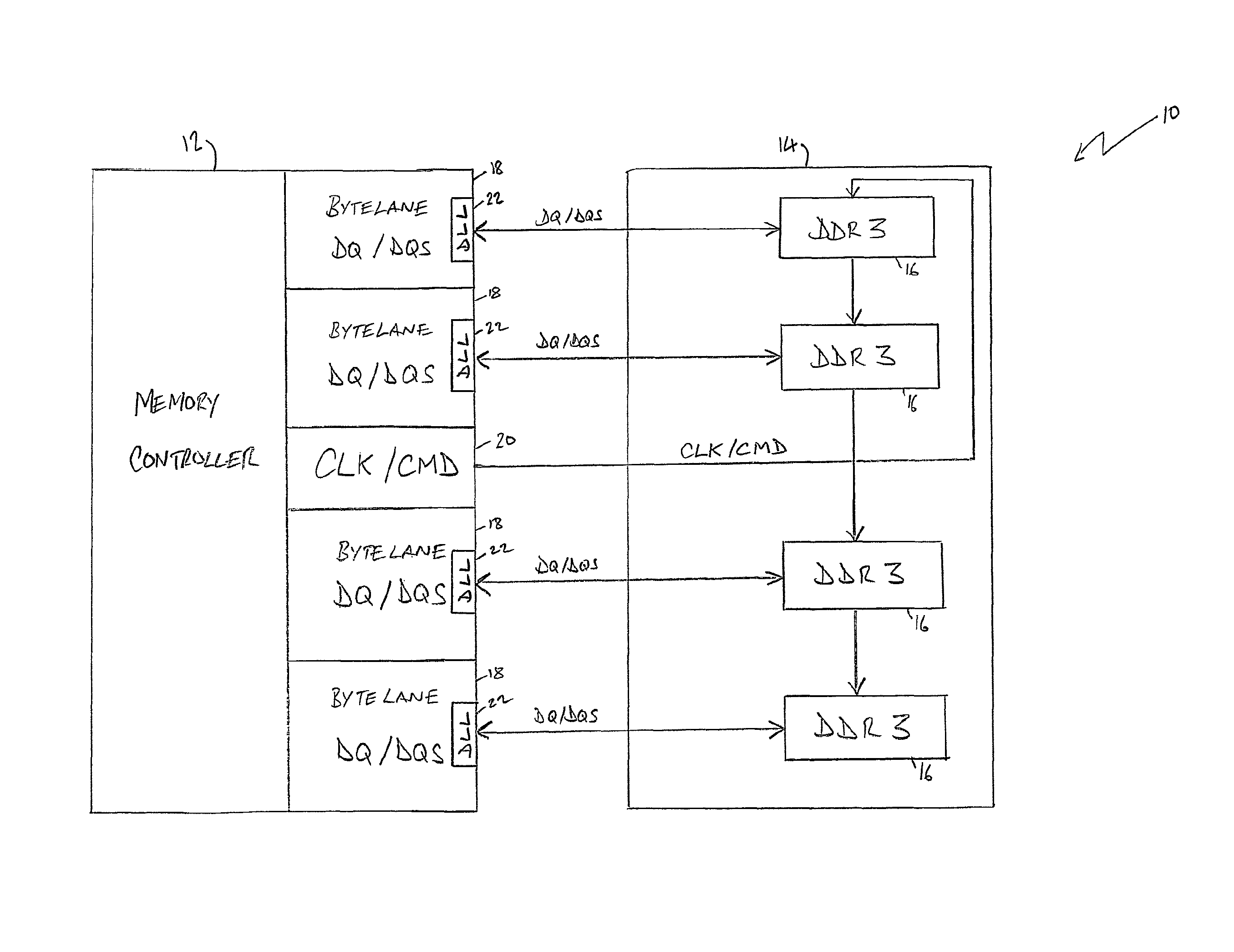
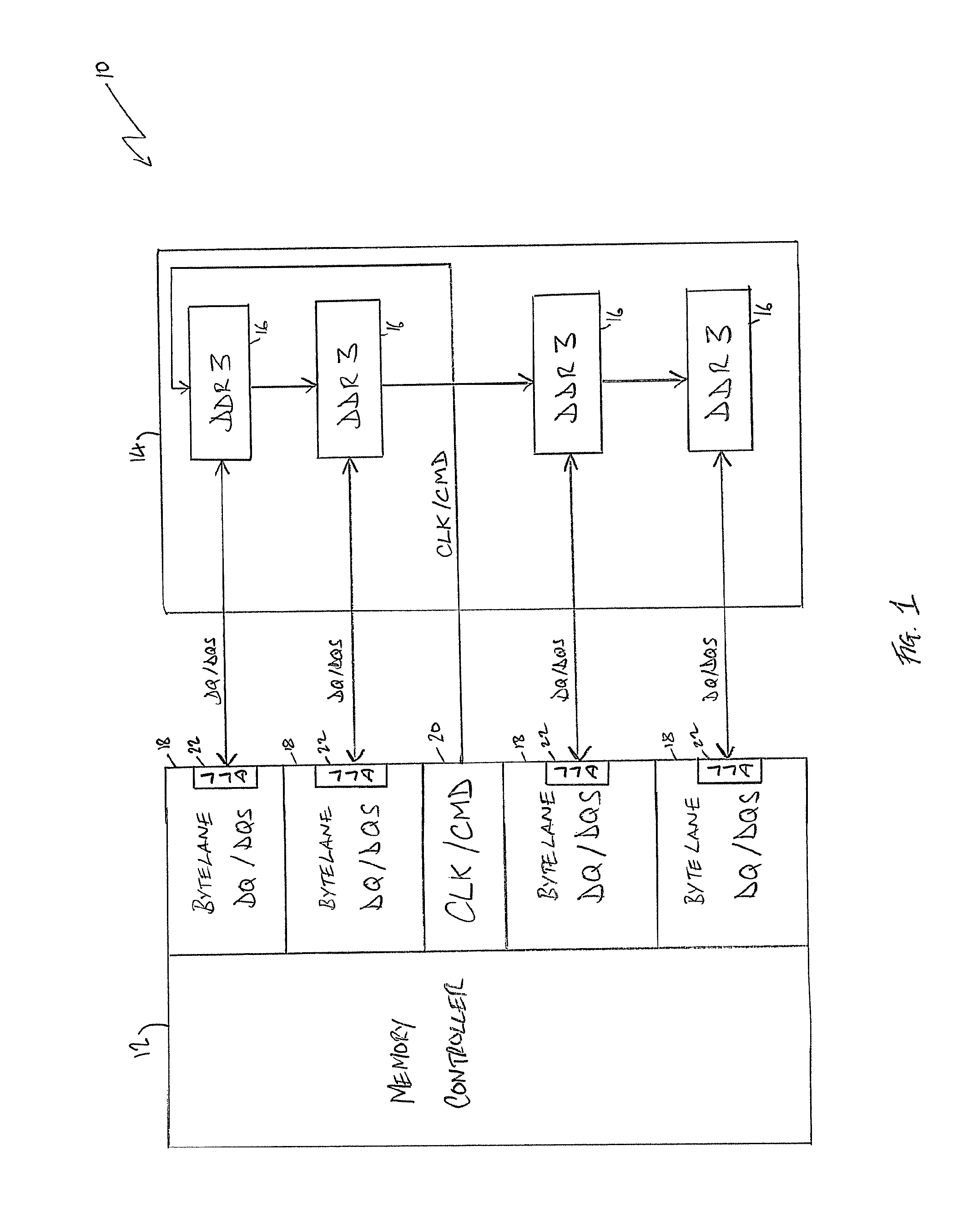
[0076]FIG. 1 schematically illustrates a DDR memory system 10, which generally comprises a memory controller integrated circuit 12 and a memory module integrated circuit 14. The memory module integrated circuit 14 comprises four DDR3 modules 16, each of which may be accessed in parallel by its own dedicated bytelane 18 provided as part of the memory controller integrated circuit 12. The memory controller integrated circuit 12 further comprises a clock / command (CLK / CMD) module 20 which is configured to transmit clock and command signals to the DDR3 modules 16. In the illustrated embodiment shown in FIG. 1, the CLK / CMD signals are transmitted between the DDR3 modules in a “fly-by” configuration to improve signal integrity (avoiding the reflections associated with a branching topology). Accordingly, the memory controller 12 can cause data to be read from one of the DDR3 modules 16 by issuing appropriate command (CMD) signals via the CLK / CMD path (in association with the clock signal CL...


PUM


Abstract

A method of calibrating a data signal receiver configured to receive a multi-bit data signal and an associated data strobe signal, wherein transitions of the data strobe signal indicate sample points for the multi-bit data signal. The method comprises the steps of: receiving, on each bit of the multi-bit data signal, a sample of a predetermined data pattern; determining, for each bit of the multi-bit data signal, a relative start timing value indicative of a start of the predetermined data pattern; determining, for each bit of the multi-bit data signal, a relative end timing value indicative of an end of the predetermined data pattern; determining, for each bit of the multi-bit data signal, a mid-point timing value halfway between the relative start timing value and the relative end timing value; applying a bit timing delay to each bit of the multi-bit data signal such that the mid-point timing values are aligned; and applying a strobe timing delay to the associated data strobe signal to align the associated data strobe signal with the aligned mid-point timing values.

Description

BACKGROUND OF THE INVENTION[0001]This application incorporates by reference the subject matter disclosed in each of the concurrently filed applications entitled “An Interface For Controlling The Phase Alignment Of Clock Signals For A Recipient Device” by Gyan Prakash et al and “A Method and Apparatus for Aligning a Clock Signal and a Data Strobe Signal in a Memory System” by Nidhar Kumar et al.”FIELD OF THE INVENTION[0002]The present invention relates to a data signal receiver. More particularly, this invention relates to the calibration of a data signal receiver to receive a multi-bit data signal and an associated data strobe signal.DESCRIPTION OF THE PRIOR ART[0003]It is known to provide a data signal receiver configured to receive a multi-bit data signal and an associated data strobe signal, wherein transitions of the data strobe signal indicate sample points for the multi-bit data signal. A typical contemporary example of such a receiver is as part of a dual data rate (DDR) dyna...

Claims


Application Information

Patent Timeline
Patent Type & Authority Patents(United States)
IPC IPC(8): G11C7/00G11C8/18
CPCG11C8/18G11C29/022G11C29/023G11C29/028G11C7/222G11C11/4076G11C2207/2254
Inventor KUMAR, NIDHIRPRAKASH, GYANVORUGU, MUNISWARA REDDY
Owner ARM LTD
Why Eureka
Try Eureka