Motorized extension pole

a motorized extension and pole technology, applied in the direction of lifting equipment, portable power-driven tools, manufacturing tools, etc., can solve the problem of not intended summary

Active Publication Date: 2015-04-21
RAMSEY MARK J +1
View PDF15 Cites 15 Cited by
  • Summary
  • Abstract
  • Description
  • Claims
  • Application Information

AI Technical Summary

Benefits of technology

[0011]In the preferred embodiment, the extension pole of this invention includes structure which prevents the second pole member from rotating, with respect to the first pole member, as it moves between its retracted and extended positions and which prevents the second pole member from rotating with respect to the first pole member, as it moves between its extended and retracted positions.

Problems solved by technology

Moreover, this Summary is not intended for use as an aid in determining the scope of the claimed subject matter.

Method used


Image

  • Motorized extension pole
  • Motorized extension pole
  • Motorized extension pole

Examples


Embodiment Construction

[0024]Embodiments are described more fully below with reference to the accompanying figures, which form a part hereof and show, by way of illustration, specific exemplary embodiments. These embodiments are disclosed in sufficient detail to enable those skilled in the art to practice the invention. However, embodiments may be implemented in many different forms and should not be construed as being limited to the embodiments set forth herein. The following detailed description is, therefore, not to be taken in a limiting sense in that the scope of the present invention is defined only by the appended claims.

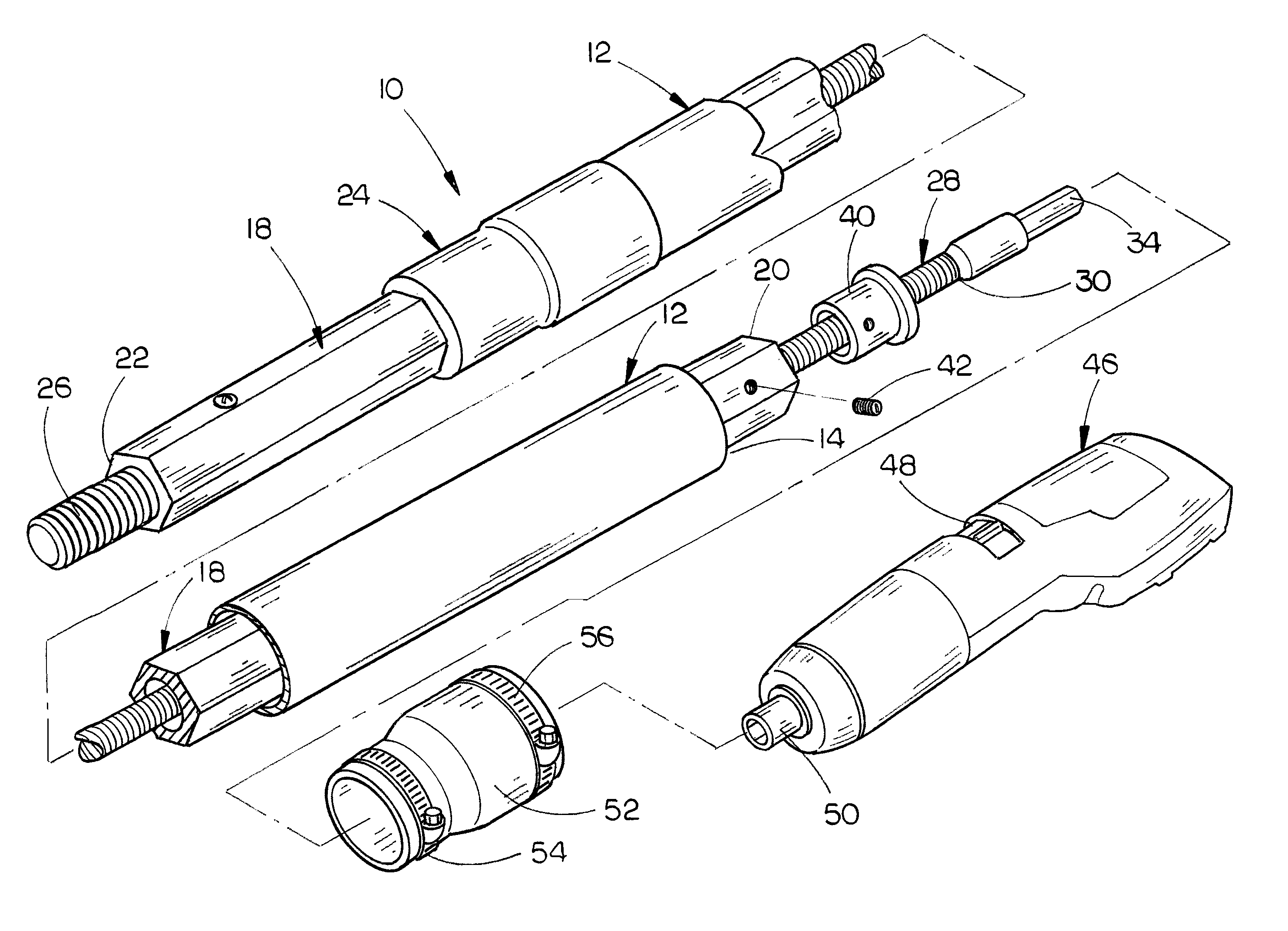
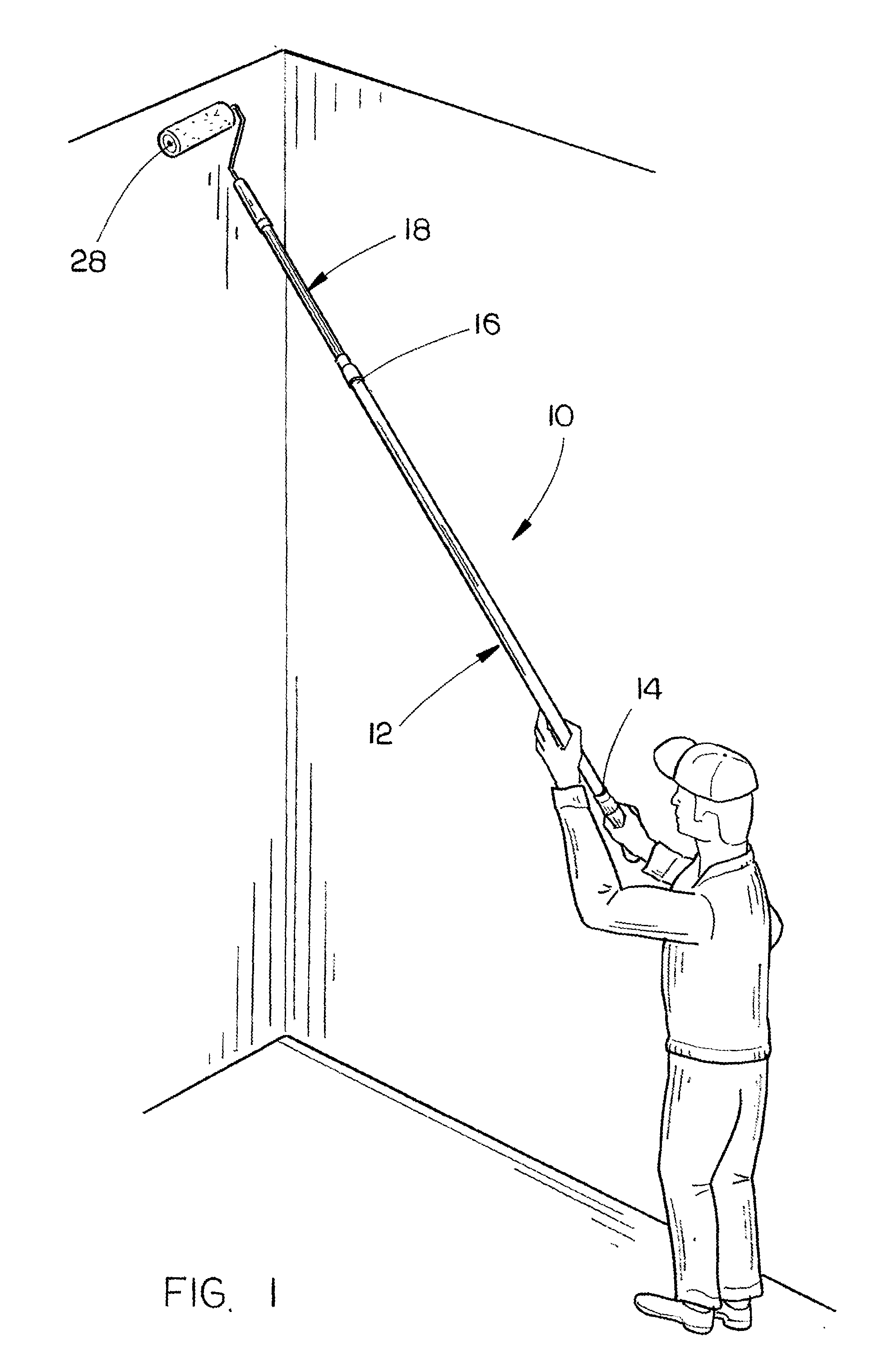
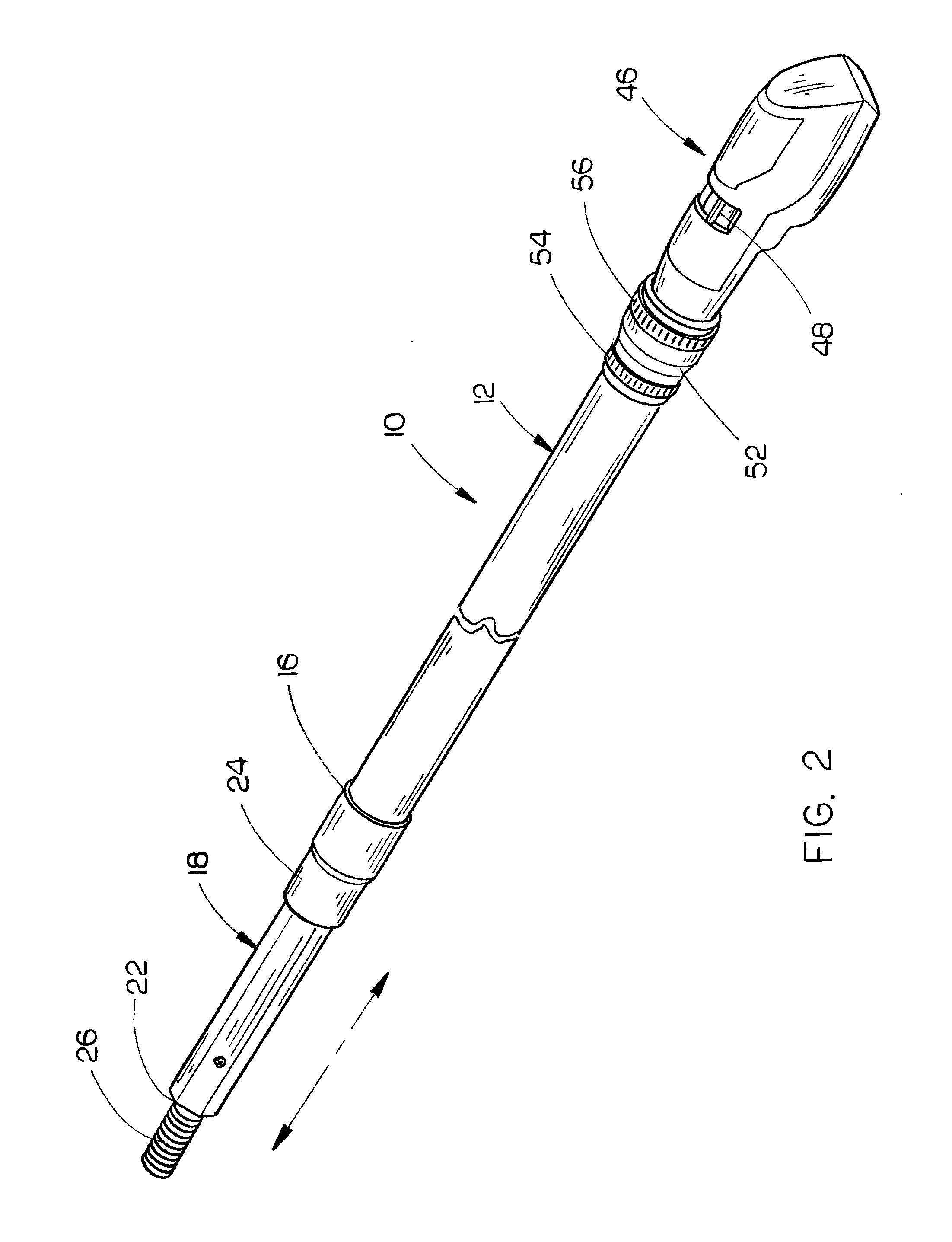
[0025]The motorized extension pole of this invention is referred to by the reference numeral 10. Extension pole 10 includes an elongated hollow outer pole member 12 having a first end and a second end. An elongated hollow inner pole member 18, having a first end 20 and a second end 22, is telescopically slidably received within pole member 12. Pole member 18 may have a hexagonal, o...


PUM


Abstract

A motorized extension pole including a first hollow pole member having a second hollow pole member telescopically mounted in said first pole member. The second pole member is selectively moved between extended and retracted positions with respect to said first pole member by a battery powered drive motor.

Description

CROSS REFERENCE TO RELATED APPLICATION[0001]This is a Continuation-In-Part Application of application Ser. No. 13 / 564,833, filed Aug. 2, 2012 entitled MOTORIZED EXTENSION POLE.BACKGROUND OF THE INVENTION[0002]1. Field of the Invention[0003]This invention relates to a length-adjustable extension pole and more particularly to a length-adjustable extension pole including a battery powered, variable speed, reversible motor which extends and retracts the inner pole member with respect to the outer pole member of the extension pole.[0004]2. Description of the Related Art[0005]Extension poles have been available for many years to enable a person to clean windows which are located above the person's normal reach. Extension poles are also used to paint areas of buildings which are located above the person's normal reach. Extension poles may also be used to string lights and ornaments on trees during the holiday season.[0006]Most extension poles include an elongated outer pole member, having ...

Claims


Application Information

Patent Timeline
Patent Type & Authority Patents(United States)
IPC IPC(8): B25G1/04A01G3/047B05C17/02B25G1/10B27B17/00E04D13/076
CPCE04D13/0765B05C17/0245A01G3/0475B27B17/00B25G1/04B25G1/10A01G3/053B05C17/0205B25F5/026B27B17/0008A01G3/086B05B15/628
Inventor RAMSEY, MARK J.RAMSEY, MARK C.
Owner RAMSEY MARK J
Why Eureka
Try Eureka