Multiple position foot massaging device

a multi-position, foot technology, applied in the field of massages, can solve the problems of inability to optimize the roller position and allow the user to change the location, and achieve the effect of easing muscle tension in the body and increasing blood flow

Active Publication Date: 2015-04-21
MCCLOREY PAUL J
View PDF26 Cites 10 Cited by
  • Summary
  • Abstract
  • Description
  • Claims
  • Application Information

AI Technical Summary

Benefits of technology

[0003]Massage is a well-known technique to increase blood flow and ease muscle tension in a person's body. Typically, in a massage, pressure is applied to a location on the body either by direct hand / finger manipulation or through a device that aids in the application of pressure.
[0008]It is an advantage of the present disclosure that the massaging device allows a user to configure the device to massage a particular part of the foot.
[0009]The massager has a first position which aligns all of the rollers in-parallel allowing a user to roll his foot or feet across a substantially horizontal row of spaced massaging rollers. The second position sets the middle roller in the elevated position, while the rear roller is lowered. The second position allows the user to roll his foot along a curved profile to better follow the curvature of the foot's arch. A third position is possible by setting the rear roller in the elevated position, while the middle roller is lowered. In this third position, the front two rollers contact a user's foot bottom, while the rear roller contacts the top of the foot. A fourth position has both the middle and rear rollers in the elevated position, in this fourth position, the massager presents a substantially flat row of rollers that are at an angle relative to the ground (from front to back roller), in this fourth position a user can roll his feet across the rollers while sitting down in substantially the same way as the first position.
[0010]It is another advantage of the present disclosure that the rollers can be supplemented with a textured outer surface to further increase and vary the pressure exhibited on the user's feet when rolled across the device.
[0011]It is still another advantage of the present disclosure that each of the rollers is comprised of two axially aligned rollers which are independently rotatable about a common axis of rotation. In this manner, a user can roll both feet simultaneously across the rollers at different speeds and / or in opposite directions.

Problems solved by technology

These massagers, however, do not allow the user to change the location of the roller(s) in the frame and therefore cannot be configured to optimize the rollers position to target a particular part of the foot.

Method used


Image

  • Multiple position foot massaging device
  • Multiple position foot massaging device
  • Multiple position foot massaging device

Examples


Embodiment Construction

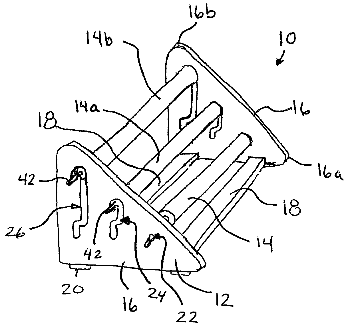
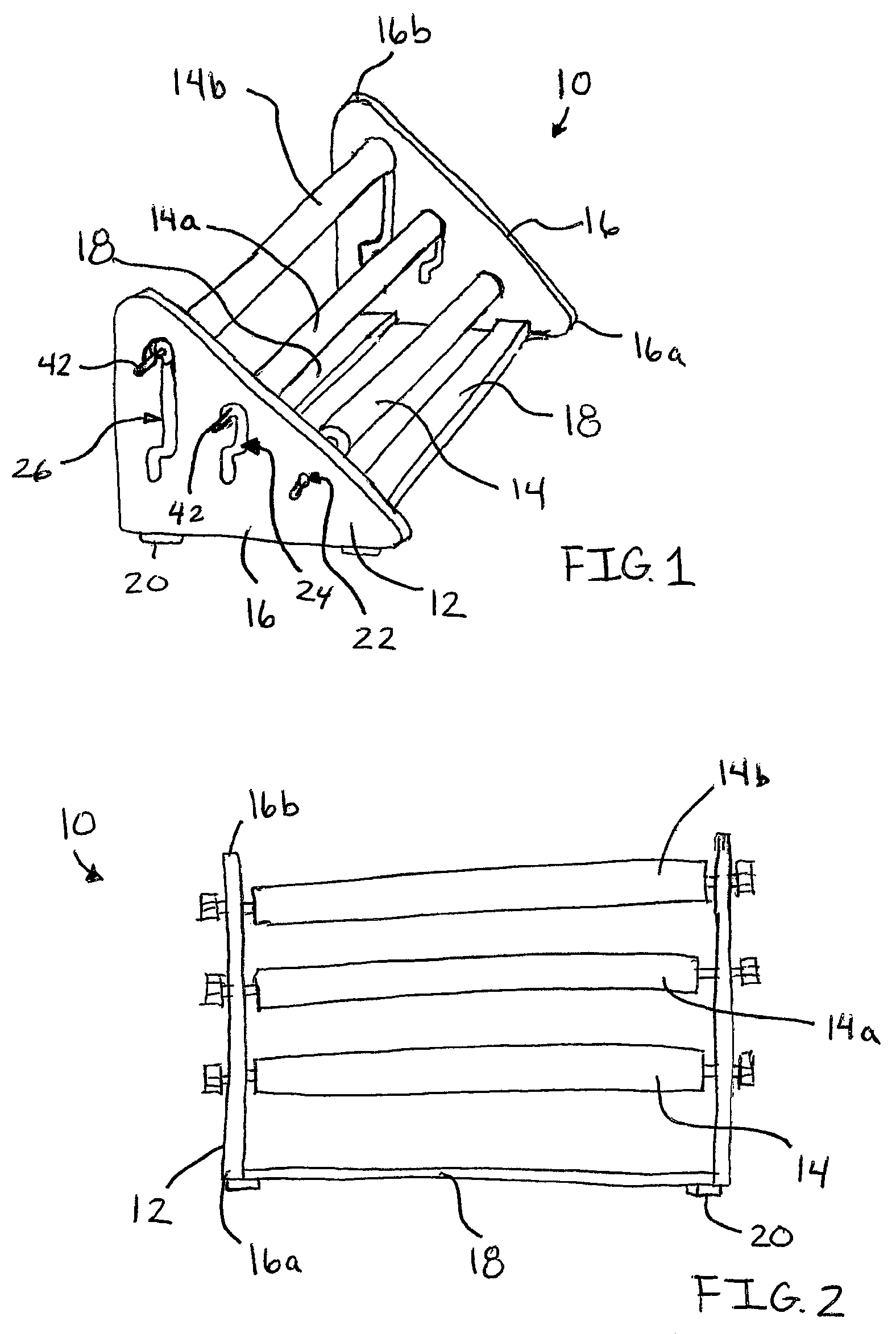
[0024]Referring now to FIGS. 1-4, a preferred foot massaging device or massager 10 is illustrated. Massager 10 includes a frame 12 which supports a plurality of rollers, denoted 14, 14a, and 14b when mounted in frame 12.

[0025]Frame 12 includes a pair of opposed vertical walls 16 which are interconnected by support bars 18 adjacent to the bottom ends of the walls. Each wall 16 is generally triangular in shape, angling from a lower-most front end 16a to an upper-most rear end 16b. Frame 12 is preferably formed from a rigid and durable material, such as metal or plastic. Resilient feet members 20 are mounted to the underside of frame 12.

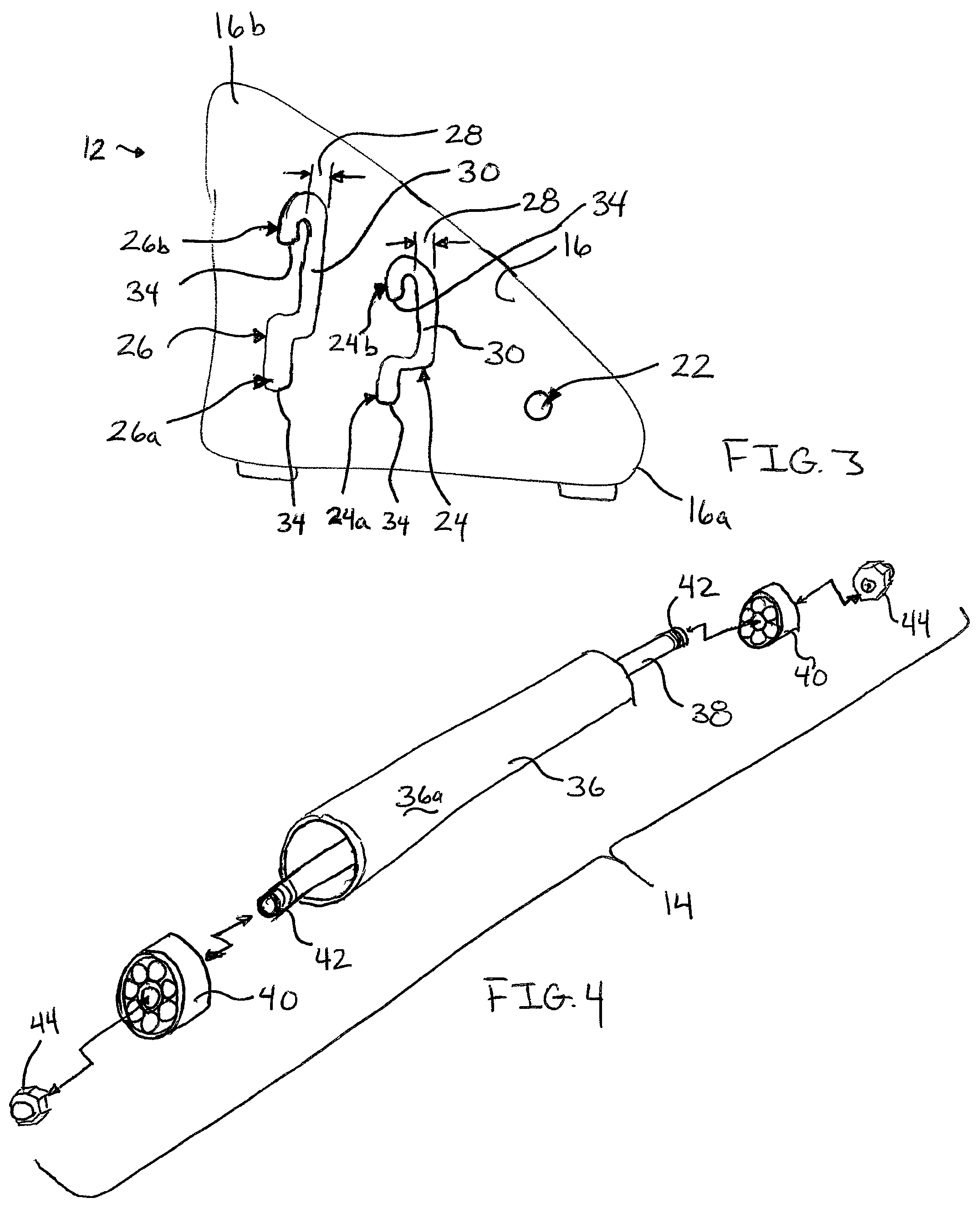
[0026]As best shown in FIG. 3, each wall 16 includes three roller mounting apertures passing between the outer and inner surfaces of the wall. Each mounting aperture has at least one roller receiving or bearing surface that is equally spaced apart from the adjacent mounting aperture. In the preferred embodiment, the front aperture 22 has a cylindrical t...


PUM


Abstract

A foot massaging device having a plurality of parallel cylindrical rollers mounted within a frame. The frame includes adjustment slots allowing the rollers to be relocated within the frame to present various massaging configurations. The foot massaging device is adjustable by seating the rearwardly disposed rollers between a raised and lowered position to configure the rollers to contact different portions of a user's foot.

Description

CROSS-REFERENCE TO RELATED APPLICATIONS[0001]This application claims priority of United States Provisional Patent Application filed Sep. 5, 2008 having Ser. No. 61 / 094,478.FIELD OF THE INVENTION[0002]This invention is related to massagers and more particularly to a user manipulated foot massaging device.BACKGROUND AND SUMMARY OF THE INVENTION[0003]Massage is a well-known technique to increase blood flow and ease muscle tension in a person's body. Typically, in a massage, pressure is applied to a location on the body either by direct hand / finger manipulation or through a device that aids in the application of pressure.[0004]Such devices include both user-manipulated tools and motorized devices which vibrate, knead, and / or rotate to manipulate a desired body part. These massage tools may either be used by the individual receiving the massage or by another person (e.g., a masseuse).[0005]One area of the body that frequently needs the therapeutic effects of massage is the foot, particul...

Claims


Application Information

Patent Timeline
Patent Type & Authority Patents(United States)
IPC IPC(8): A61H15/00
CPCA61H15/00A61H2015/0014A61H2201/169A61H2205/12
Inventor MCCLOREY, PAUL J.
Owner MCCLOREY PAUL J
Why Eureka
Try Eureka