Cleaning device and image forming apparatus

a technology of cleaning device and image forming apparatus, which is applied in the direction of optics, instruments, electrography/magnetography, etc., can solve the problems of bending the cleaning blade back, unable to obtain desired pressure, and removing residual toner, etc., and achieves the effect of suppressing a change in pressur

Active Publication Date: 2015-04-21
CANON KK
View PDF9 Cites 0 Cited by
  • Summary
  • Abstract
  • Description
  • Claims
  • Application Information

AI Technical Summary

Benefits of technology

[0009]In a cleaning device which pressurizes a swingably supported cleaning blade by a compression spring, it is desirable to provide a cleaning device and an image forming apparatus capable of suppressing a change in pressure, which is caused because a pressure position is not constant according to a swing position of a blade.

Problems solved by technology

However, in a case where the pressure of the cleaning blade is changed, there arises a problem in that the cleaning blade is bent back or the residual toner is taken out by a poor cleaning.
Hence, a desired pressure cannot be obtained.
Therefore, it is difficult to stably apply a pressure.

Method used


Image

  • Cleaning device and image forming apparatus
  • Cleaning device and image forming apparatus
  • Cleaning device and image forming apparatus

Examples


first embodiment

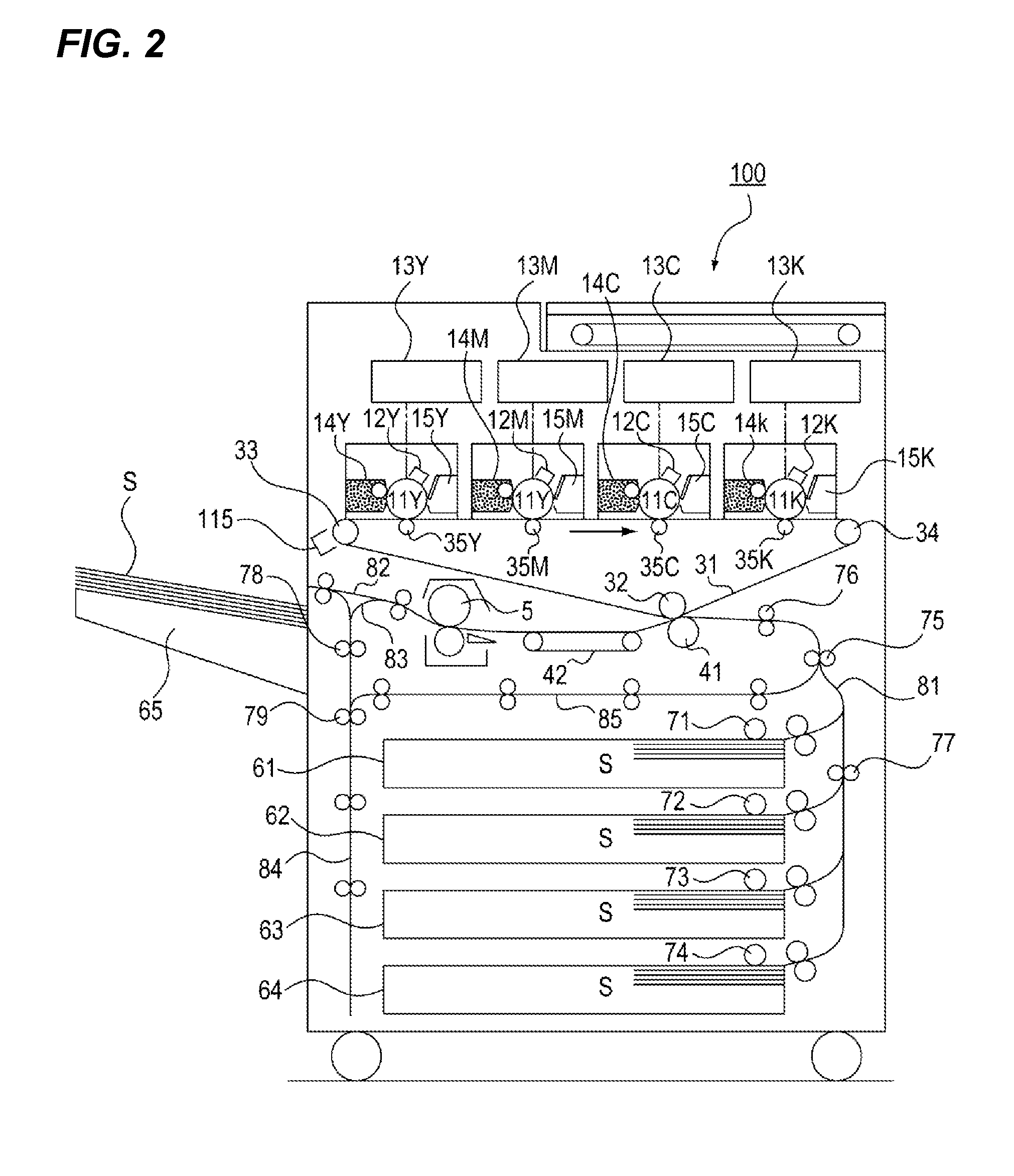
[0020]A first embodiment of a cleaning device and an image forming apparatus according to the present invention will be described with reference to the drawings. FIG. 2 is a configuration diagram of an image forming apparatus according to the present embodiment.

[0021]As illustrated in FIG. 2, in an image forming apparatus 100 of the present embodiment, electrostatic latent images are formed in such a manner that photosensitive drums (image bearing members) 11Y to 11K, of which surfaces are uniformly charged by charging devices 12Y to 12K, are exposed to a laser according to image information by exposure devices 13Y to 13K.

[0022]The electrostatic latent images formed on the photosensitive drums 11 are developed into toner images using respective color toners by developing devices 14Y to 14K. The respective developed color toner images are primarily transferred by primary transfer rollers 35Y to 35K, while being overlapped on an intermediate transfer belt (intermediate transfer member...

second embodiment

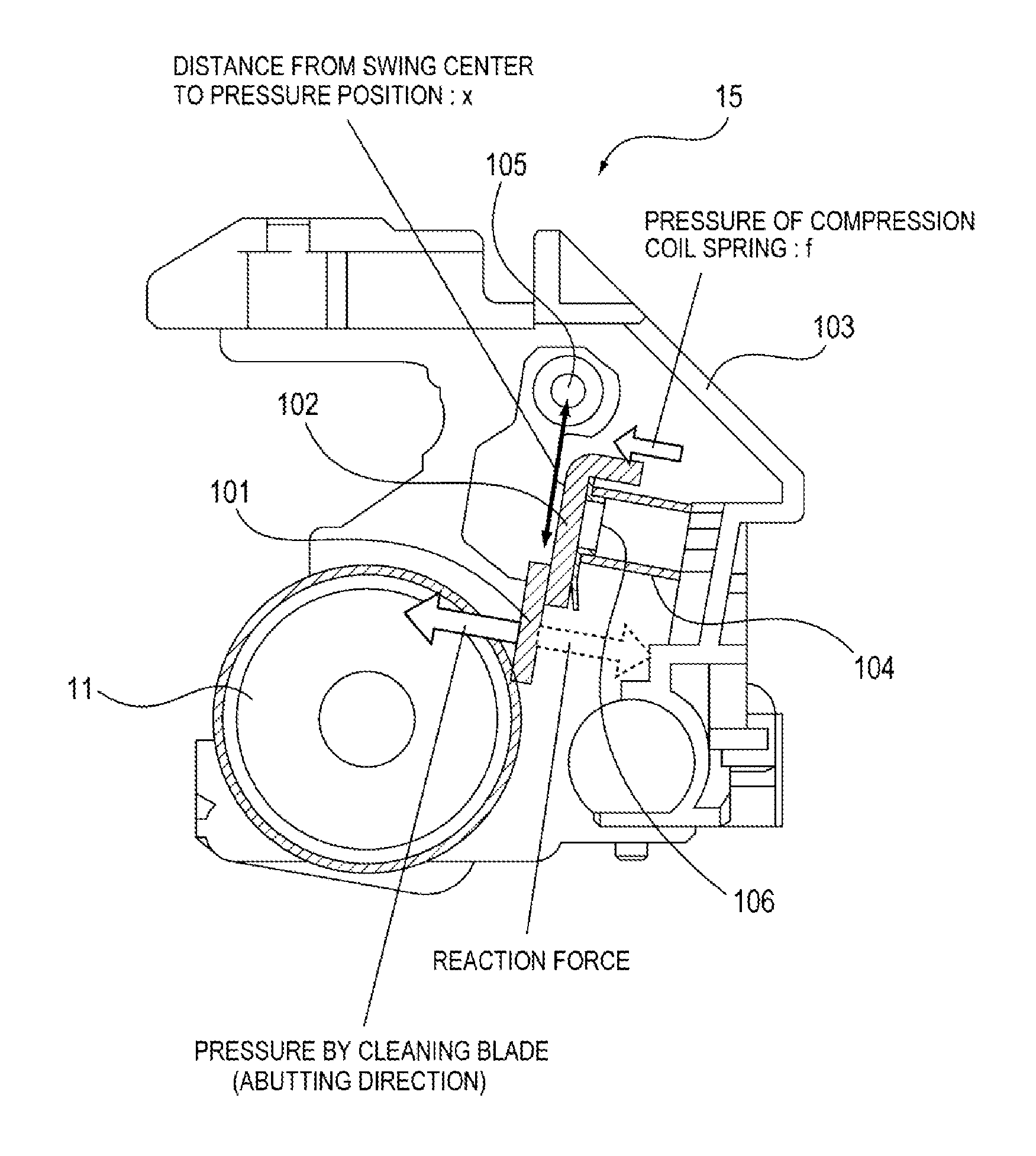
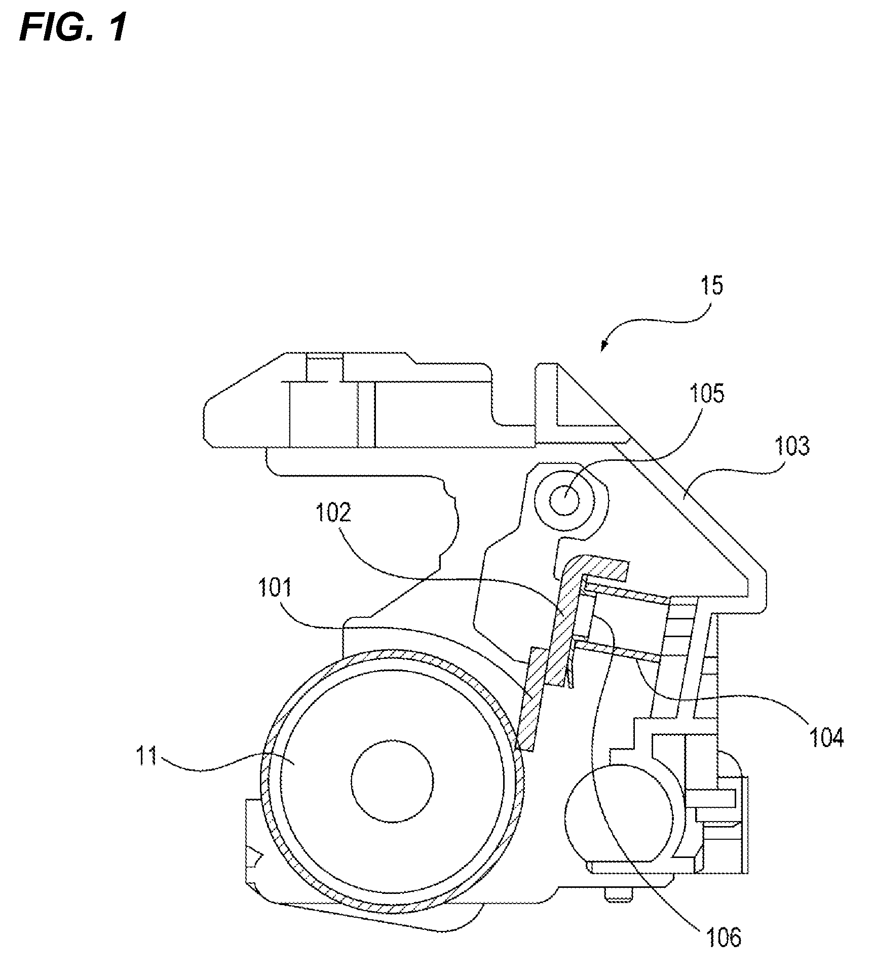
[0039]Next, a second embodiment of a cleaning device and an image forming apparatus according to the present invention will be described with reference to the drawings. Parts overlapped with the description of the first embodiment are assigned with the same reference numerals, and a description thereof will not be repeated. FIG. 6 is a configuration diagram of the cleaning device 15 according to the present embodiment.

[0040]As illustrated in FIG. 6, the cleaning device 15 of the present embodiment includes a positioning boss (second regulating portion) 108 provided on the cleaning container 103 side of the cleaning device 15 of the first embodiment. That is, the positioning boss 108 is provided in an opposite portion facing the holding plate 102, with the compression coil spring 104 being disposed therebetween. The positioning boss 108 is engaged with the other end of the compression coil spring 104 (cleaning container 103 side), with a predetermined gap L being provided between the...


PUM


Abstract

A representative configuration of a cleaning device and an image forming apparatus according to the present invention includes: a photosensitive drum which bears a toner image; a cleaning blade which abuts against the photosensitive drum and removes a toner remained in the photosensitive drum; a compression coil spring which is compressed to pressurize the cleaning blade against the photosensitive drum; and a positioning boss which is arranged to face the compression coil spring, with a predetermined gap being provided therebetween, allows a movement in a direction perpendicular to a compression direction of the compression coil spring, and regulates a movement of the compression coil spring such that the compression coil spring is not moved by more than a predetermined amount in the direction perpendicular to the compression direction of the compression coil spring.

Description

BACKGROUND OF THE INVENTION[0001]1. Field of the Invention[0002]The present invention relates to a cleaning device which cleans an image forming apparatus or an intermediate transfer member, and an image forming apparatus including the same.[0003]2. Description of the Related Art[0004]Some of cleaning devices used for image forming apparatuses, such as printers, copying machines, and facsimile machines, include a cleaning blade (cleaning member) which cleans an image bearing member or an intermediate transfer member.[0005]For example, in an image forming apparatus using an electrophotographic system, a toner image is primarily transferred from a photosensitive drum (image bearing member) to an intermediate transfer belt (intermediate transfer member), and is secondarily transferred from the intermediate transfer belt to a sheet. At the time of the transfer, a small amount of toner remains in the photosensitive drum or the intermediate transfer belt. The toner remained in the photose...

Claims


Application Information

Patent Timeline
Patent Type & Authority Patents(United States)
IPC IPC(8): G03G21/00
CPCG03G21/0029
Inventor MATSUMURA, TAKUYA
Owner CANON KK
Why Eureka
Try Eureka