Photographic fixing roller, fixing device and image forming device

A technology of fixing roller and elastic layer, which is applied in the field of fixing roller, can solve the problems of expansion of difference, accelerated deterioration of heating belt, deformation of heating belt, etc.

Inactive Publication Date: 2014-05-21
RICOH KK
View PDF5 Cites 0 Cited by
  • Summary
  • Abstract
  • Description
  • Claims
  • Application Information

AI Technical Summary

Problems solved by technology

However, in the conventional positive crown-shaped fixing roller having such a pair of positive conical surfaces S, it is necessary to set the positive conical step difference Ht to the above-mentioned deviation preventing value Hs for It is a relatively large value to reliably prevent the deflection phenomenon of the heating belt. When the deflection prevention value Hs is ensured by a pair of right conical surfaces S provided in the fixing roller, the fixing roller 901 The difference between the outer diameter a of the center O and the outer diameters b, c of the two ends expands, resulting in a problem of unevenness in the width or pressure of the nip formed between the fixing roller 901 and the pressure roller to be pressed.
[0015] In addition, to solve this problem, as shown in Patent Document 3, the shape of the fixing roller is adapted to the shape of the fixing roller by forming the fixing roller into a reverse crown shape in which the outer diameter near the center is small and gradually increases toward both ends. The difference between the outer diameter of the center and the outer diameters of both ends is enlarged, and the width and pressure of the nip portion can be made uniform, but because this technology cannot solve the above-mentioned difference itself, the above-mentioned difference is caused by the fixing roller. The difference between the length of the outer circumference near the center and the length of the outer circumference near both ends will cause the stress in the heating belt to bend in the width direction and cause the deformation of the heating belt, thereby accelerating the deterioration of the heating belt. question
That is to say, the deterioration and deflection of the heating tire and the uniformity of the clamping part cannot be solved at the same time

Method used


Image

  • Photographic fixing roller, fixing device and image forming device
  • Photographic fixing roller, fixing device and image forming device
  • Photographic fixing roller, fixing device and image forming device

Examples


no. 1 approach

[0085] Below, refer to figure 1 Referring to FIG. 3 , a first embodiment of the fixing roller according to the present invention will be described.

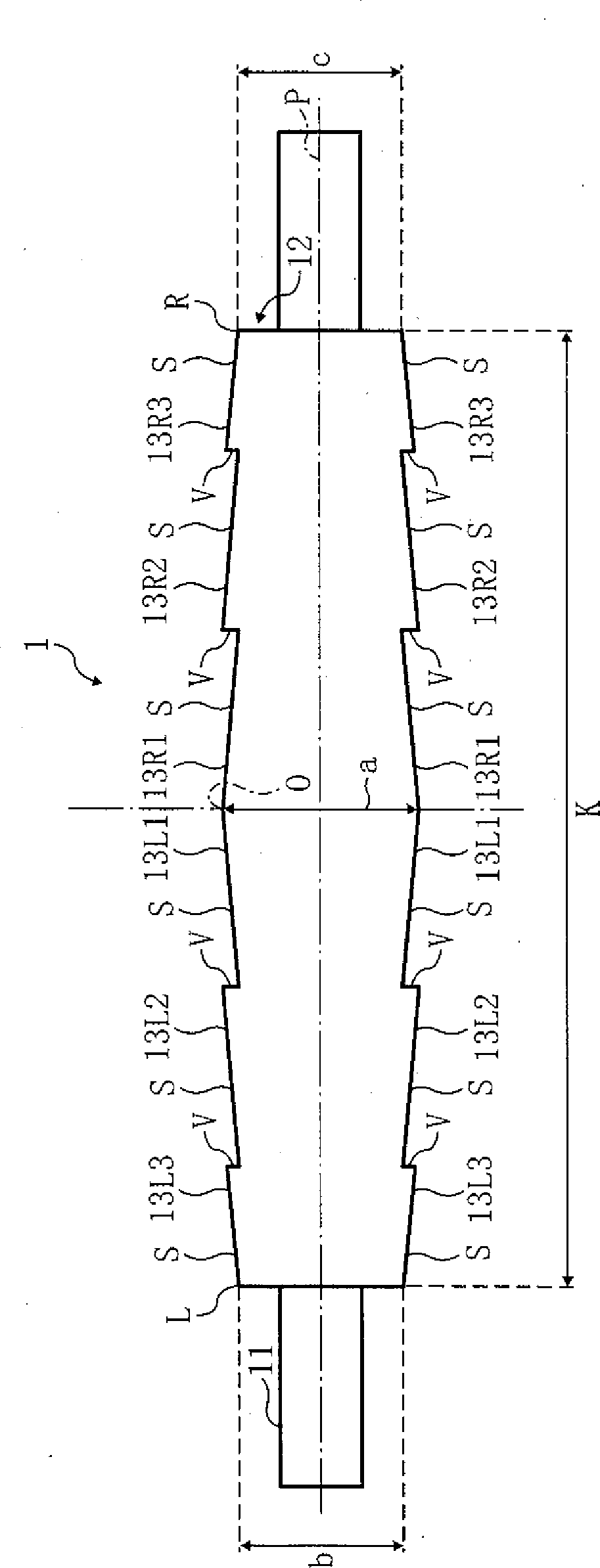
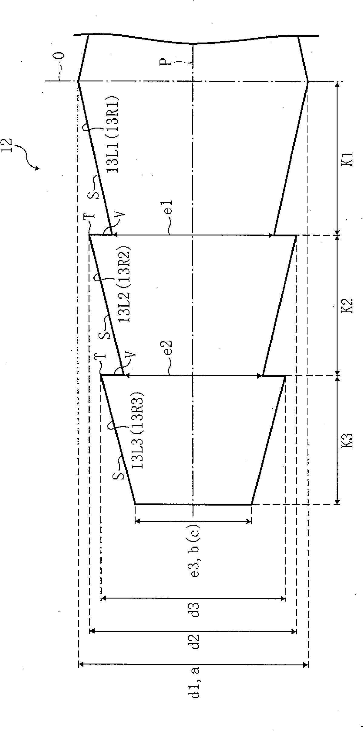
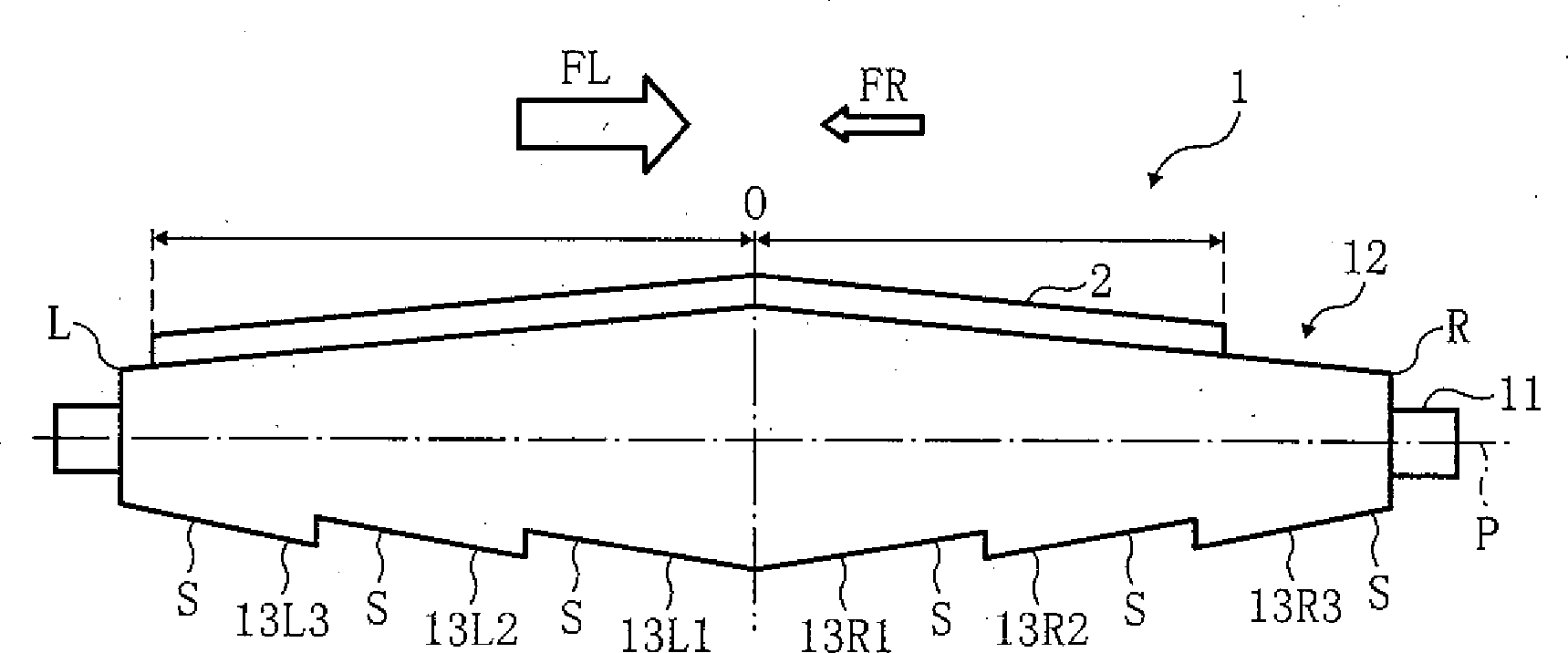
[0086] figure 1 The illustrated fixing roller 1 includes a mandrel 11 and an elastic layer 12 . The mandrel 11 may be made of iron to form a hollow cylindrical shape. The mandrel 11 is installed in a fixing device 116 described later so as to be rotatable about its axis. The elastic layer 12 can be made of an elastic member such as foamed silicone rubber, is formed in a cylindrical shape, is closely overlapped in the outer peripheral surface of the mandrel 11 , and is arranged coaxially with the mandrel 11 . Such as figure 1 , figure 2 As shown, in the outer peripheral surface (surface portion) of the elastic layer 12, a plurality of protrusions 13 (13L1-13L3, 13R1-13R3) protruding in the outward direction are provided.

[0087] Each of these protrusions 13 is provided with a right conical surface S which is high on the...

no. 2 approach

[0115] A second embodiment of the fixing roller according to the present invention will be described below. Since the fixing roller of the second embodiment has the same shape as that of the first embodiment, only the dimensions of each part are different, so refer to the description of the above-mentioned first embodiment. figure 1 , figure 2 .

[0116] In the fixing roller 1 of the second embodiment, the shapes of the right conical surfaces S of all the convex portions 13 ( 13L1 - 13L3 , 13R1 - 13R3 ) are the same. Specifically, the right conical step differences Ht1-Ht3 in the right conical surface S of each convex portion 13 are the same, and the total lengths K1, K2, and K3 of the convex portions 13 are all the same.

[0117] In this way, by making the shape of the right conical surface S of all the protrusions 13, that is, the angle with respect to the axial direction of the elastic layer in the right conical surface S and the length of the generatrix of the right co...

no. 3 approach

[0121] Below, refer to Figure 4-Figure 6 A third embodiment of the fixing roller according to the present invention will be described.

[0122] Figure 4 The illustrated fixing roller 1A includes a mandrel 11 and an elastic layer 12A. The formation of the mandrel 11 is the same as that of the first embodiment described above. The elastic layer 12A may be made of an elastic member such as foamed silicon, and is formed in a cylindrical shape, closely overlapped on the outer peripheral surface of the mandrel 11 and arranged coaxially with the mandrel 11 . Such as Figure 4 , Figure 5 As shown, in the outer peripheral surface (surface portion) of the elastic layer 12A, a plurality of protrusions 14 ( 14L1 - 14L3 , 14R1 - 14R3 ) protruding outward are provided.

[0123] Each of these protrusions 14 is provided with a right conical surface S that is high on the center O side in the axial direction P of the elastic layer 12A and is low on the end L, R sides. Among the plurali...


PUM


Abstract

The invention provides a photographic fixing roller, a fixing device and an image forming device, which can keep the uniformity of a clamping part while preventing a wheel belt from deteriorating and deviating. A flexible layer (12) of the photographic fixing roller (1) is provided with multiple projections (13) continuously extending from the axial center O of the flexible layer to end parts L and R and symmetrical to the center O. Each projection (13) comprises a right conical surface S with a higher end adjacent to the center O and a lower end adjacent to the ends L and R. Namely, in the photographic fixing roller, the multiple right conical surfaces S are continuously arranged from the center O to the ends L and R with the center O as the symmetrical point. The projections (13) are defined in a way that the sum of the right conical step difference Ht in each right conical surface S is a necessary predetermined deviation preventing value for preventing heating wheel belts from deviating.

Description

technical field [0001] The present invention relates to a fixing roller for fixing an unfixed toner image in an electrophotographic copier, printer, and facsimile, a fixing device having the fixing roller, and an image forming apparatus having the fixing device. Background technique [0002] In photocopiers, printers, facsimiles, and other image forming devices using electrophotography, a fixing device is installed to heat the toner image that has been developed and has not been fixed on a sheet-like recording medium such as transfer paper or OHP. . One of the fixing methods employed in this fixing device is the heated belt fixing method. In this heating belt fixing method, an endless heating belt that is heated by heating means such as a radiator is rotatably stretched over the fixing roller and is arranged in parallel at a distance from the fixing roller. The support roller, and the heating belt is sandwiched between them so that the pressure roller is pressed into the f...

Claims


Application Information

Patent Timeline
Patent Type & Authority Patents(China)
IPC IPC(8): G03G15/20
Inventor 须藤克典
Owner RICOH KK
Why Eureka
Try Eureka