Stator for rotating electric machine

a technology of rotating electric machines and rotating shafts, which is applied in the direction of dynamo-electric machines, electrical apparatus, windings, etc., can solve the problems of increasing the noise generated by the cooling fan rotation, damaging the connection parts, and uneven bridging wires, so as to reduce the noise of the cooling fan, improve the environmental resistance of the rotating electric machine, and reduce the effect of pressure variation

Active Publication Date: 2016-10-04
DENSO CORP
View PDF5 Cites 0 Cited by
  • Summary
  • Abstract
  • Description
  • Claims
  • Application Information

AI Technical Summary

Benefits of technology

[0010]Consequently, with the at least one protective wall, when the stator is subjected to the flow of cooling air created by a cooling fan of the rotating electric machine which is disposed radially inside the stator, it is possible to suppress pressure variation on the radially inside of the connection portions in the circumferential direction of the stator core, thereby reducing the fan noise generated during rotation of the cooling fan. Moreover, it is also possible to protect the connection portions from foreign matter which flows to the stator from the radially inside along with the flow of cooling air created by the cooling fan. As a result, it is possible to improve the environmental resistance of the rotating electric machine.

Problems solved by technology

Consequently, the radial distances of the bridging wires from the center of rotation of the rotating electric machine become non-uniform; thus a radially inner peripheral surface of the stator coil which is defined by the connection portions and the bridging wires becomes not smooth.
As a result, when the connection portions and the bridging wires are subjected to the flow of cooling air created by a cooling fan of the rotating electric machine which is disposed radially inside the stator, pressure variation may occur on the radially inside of the connection portions and the bridging wires in the circumferential direction of the stator core, thereby increasing the fan noise generated during rotation of the cooling fan.
Consequently, foreign matter, such as dust and electrolytic solution (e.g., saltwater) may flow to the connection portions along with the flow of cooling air created by the cooling fan, thereby damaging the connection portions.

Method used


Image

  • Stator for rotating electric machine
  • Stator for rotating electric machine
  • Stator for rotating electric machine

Examples


Embodiment Construction

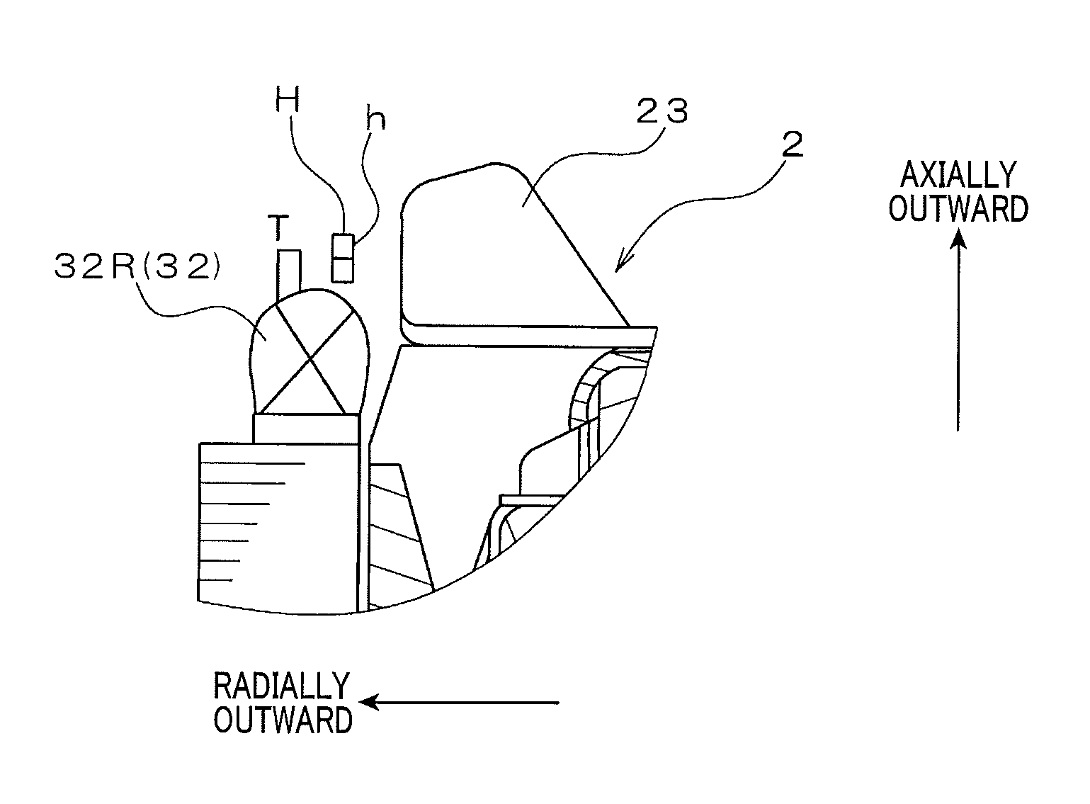
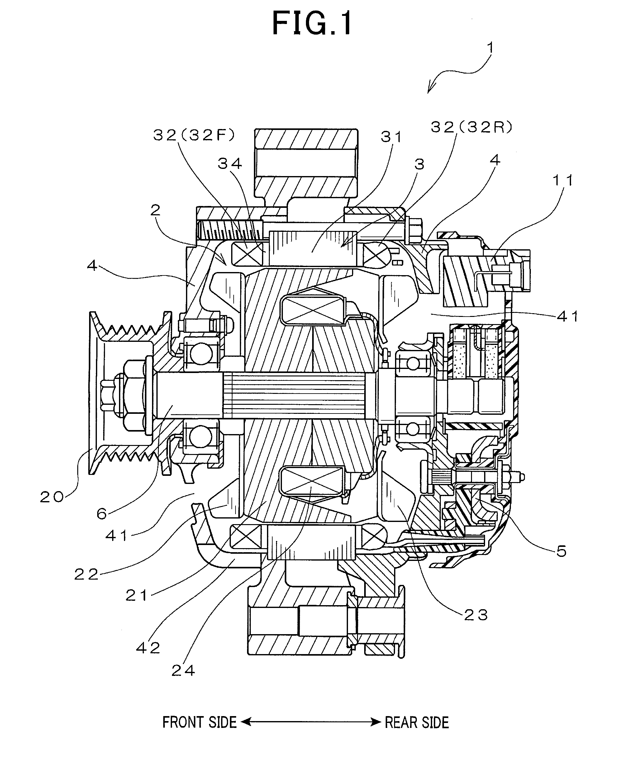
[0031]FIG. 1 shows the overall configuration of an automotive alternator 1 which includes a stator 3 according to an exemplary embodiment. The alternator 1 is designed to be used in a motor vehicle, such as a passenger car or a truck.

[0032]As shown in FIG. 1, the alternator 1 includes, in addition to the stator 3, a rotor 2, a frame 4, a rectifier 5, a voltage regulator 11 and a pulley 20.

[0033]The rotor 2 includes a rotating shaft 6, a pair of Lundell-type magnetic pole cores 21 and a field coil 24. The rotating shaft 6 is rotatably supported by the frame 4 via bearings. The rotating shaft 6 has the pulley 20 mounted on a front end portion (i.e., a left end portion in FIG. 1) thereof, so that it can be driven by an internal combustion engine (not shown in the figures) of the vehicle via the pulley 20. Each of the magnetic pole cores 21 has a plurality of magnetic pole claws. The field coil 24 is made of, for example, an insulation-treated copper wire and wound into an annular shape...


PUM


Abstract

A stator includes an annular stator core, a stator coil and at least one protective wall. The stator core has a plurality of slots formed therein. The slots are spaced from one another in a circumferential direction of the stator core. The stator coil is comprised of a plurality of windings mounted on the stator core. The windings are connected in a predetermined manner to form a plurality of connection portions therebetween. The connection portions are located outside the slots of the stator core on one axial side of the stator core. The at least one protective wall is provided radially inside the connection portions of the stator coil so as to shield the connection portions from the radially inside of the stator.

Description

CROSS-REFERENCE TO RELATED APPLICATION[0001]This application is based on and claims priority from Japanese Patent Application No. 2013-182717 filed on Sep. 4, 2013, the content of which is hereby incorporated by reference in its entirety into this application.BACKGROUND[0002]1 Technical Field[0003]The present invention relates to stators for rotating electric machines that are used in, for example, motor vehicles as electric motors and electric generators.[0004]2 Description of Related Art[0005]Japanese Patent Application Publication No. JP2006-280121A discloses a stator for a rotating electric machine. The stator includes a stator coil that is comprised of a pair of first and second three-phase coils. Each of the first and second three-phase coils includes a plurality of phase windings that are connected in a predetermined manner to form a plurality of connection portions therebetween. The stator coil is mounted on an annular stator core of the stator so that: the first and second ...

Claims


Application Information

Patent Timeline
Patent Type & Authority Patents(United States)
IPC IPC(8): H02K3/28H02K9/00H02K3/48H02K3/44H02K3/38H02K3/12H02K9/06
CPCH02K3/28H02K3/12H02K3/38H02K3/44H02K3/48H02K9/00H02K9/06
Inventor SEKIYAMA, YOUSUKE
Owner DENSO CORP
Why Eureka
Try Eureka