Fluid control valve

A fluid control valve and cylinder technology, which is applied to fluid pressure actuating devices, multi-port valves, valve devices, etc., can solve the problem of increasing the opening speed of the lift-lock poppet valve 9, and achieve suppression of pressure loss and impact. sound effect

Active Publication Date: 2014-11-26
SHIMADZU SEISAKUSHO CO LTD
View PDF5 Cites 0 Cited by
  • Summary
  • Abstract
  • Description
  • Claims
  • Application Information

AI Technical Summary

Problems solved by technology

However, in order to solve this problem, when the diameter of the hole 9b is made large, the speed of the opening operation of the lift lock poppet valve 9 is also increased, and the plug 8a that accommodates the lift lock poppet valve 9 is violently collided to generate a large diameter. Other adverse phenomena of the impact sound

Method used


Image

  • Fluid control valve
  • Fluid control valve
  • Fluid control valve

Examples


Embodiment Construction

[0062] Below, refer to figure 1 and figure 2 Preferred embodiments of the present invention will be described. Here, the same names and symbols are used for parts corresponding to the above-mentioned conventional fluid control valves.

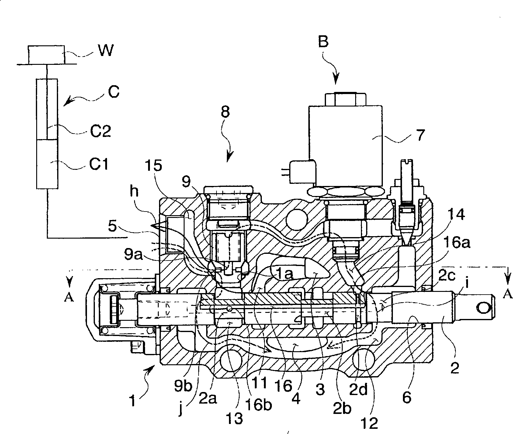
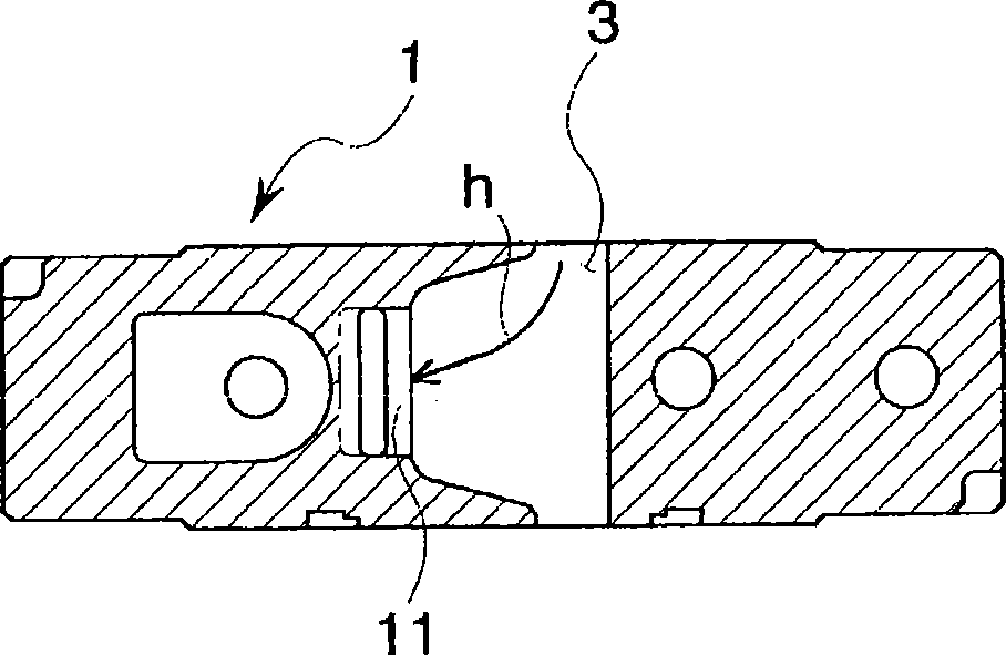
[0063] The fluid control valve B of this embodiment is mounted on a forklift, which has figure 1 A side sectional view showing, figure 2 Expressed figure 1 A-A sectional view of the structure.

[0064] Specifically, this fluid control valve B has substantially the same structure as the above-mentioned conventional fluid control valve BB. That is, the fluid control valve B includes a valve main body 1 and a valve stem 2 .

[0065] The valve main body 1 is equipped with: a sleeve 6, which is connected to the suction port 3 for sucking the working fluid, the discharge port 4 for discharging the working fluid, and the cylinder port 5 for outputting the working fluid to the lifting cylinder C; the solenoid valve 7, which is opened closin...


PUM


Abstract

A fluid control valve wherein a main valve body includes: a high-pressure passage providing communication between a suction port and a sleeve in which a spool is fitted; a tank passage providing communication between a discharge port and the sleeve; a lift lock poppet located between the sleeve and a cylinder port and assuming an open position for providing communication between the sleeve and the cylinder port; a hydraulic fluid discharge passage providing communication between a back-pressure chamber provided within the lift lock poppet and the sleeve; a hydraulic fluid delivery passage located between the sleeve and the lift lock poppet; a cylinder passage located between the lift lock poppet and the cylinder port that communicates with the hydraulic fluid delivery passage when the lift lock poppet is in the open position, and a communication passage providing communication between the hydraulic fluid discharge passage and the hydraulic fluid delivery passage.

Description

technical field [0001] The present invention relates to a fluid control valve, which changes the flow path of fluid by displacing a valve stem in a valve main body, and controls the supply and discharge of fluid to a lifting cylinder. Background technique [0002] At present, there are fluid control valves that control the supply and discharge of fluid to and from the lift cylinder by changing the flow path of the fluid by displacing the valve stem in the valve body. image 3 The side sectional view shown, Figure 4 as shown image 3 The X-X cross-sectional view of the structure. [0003] That is, the fluid control valve BB includes a valve main body 1 having a suction port 13 connected to suction of the working fluid, a discharge port 4 for discharging the working fluid, and a cylinder for outputting the working fluid to the lift cylinder C and a valve stem 2. The sleeve 6 of the body port 5; the solenoid valve 7 that opens and closes the flow path between the cylinder por...

Claims


Application Information

Patent Timeline
Patent Type & Authority Patents(China)
IPC IPC(8): F15B11/08
CPCF15B13/0417F15B2211/30515F15B13/0405F16K11/0716F15B13/0402Y10T137/87217Y10T137/86702
Inventor 西口裕己
Owner SHIMADZU SEISAKUSHO CO LTD
Why Eureka
Try Eureka