Ant bait dispenser

a technology of ant bait and dispenser, which is applied in the field of ant bait dispenser, can solve the problems of difficult to address particular insect infestations with single toxic bait, and achieve the effects of prolonging the useful life of a particular dispenser, preventing sealing puncture, and retarding the evaporation process

Inactive Publication Date: 2015-04-28
MCLAUGHLIN GORMLEY KING CO INC
View PDF20 Cites 19 Cited by
  • Summary
  • Abstract
  • Description
  • Claims
  • Application Information

AI Technical Summary

Benefits of technology

[0005]The dispenser for liquid toxic insect baits of this invention has a top with foil-sealed liquid bait compartments. The top is mounted on a base for axial motion towards the base on a shaft. The base has protruding posts disposed beneath each sealed bait compartment. A tear-off strip on the base keeps the foil-seal sufficiently above the posts to prevent puncturing of the seal. Once the tear-off strip is removed, the top can be advanced towards the base to simultaneously puncture the foil seal on all the compartments, thereby permitting the toxic bait fluid to flow along the posts and be retained by a sponge-like liquid retaining member, formed, for example, of hydrophillic open cell polyurethane foam. Projecting flanges of the container shield the liquid retaining members from direct sunlight and breezes, thereby retarding the process of evaporation and extending the useful life of a particular dispenser. The top may alternatively be hinged to the base. Or, the top may be mounted around a threaded post on the base, and positioned beneath a cap which is engaged the threaded post such that rotation of the cap drives the top into engagement with the base posts.

Problems solved by technology

Certain insect pests will exhibit variations in dietary preferences, making it difficult to address particular insect infestations with a single toxic bait.

Method used


Image

  • Ant bait dispenser
  • Ant bait dispenser
  • Ant bait dispenser

Examples


Embodiment Construction

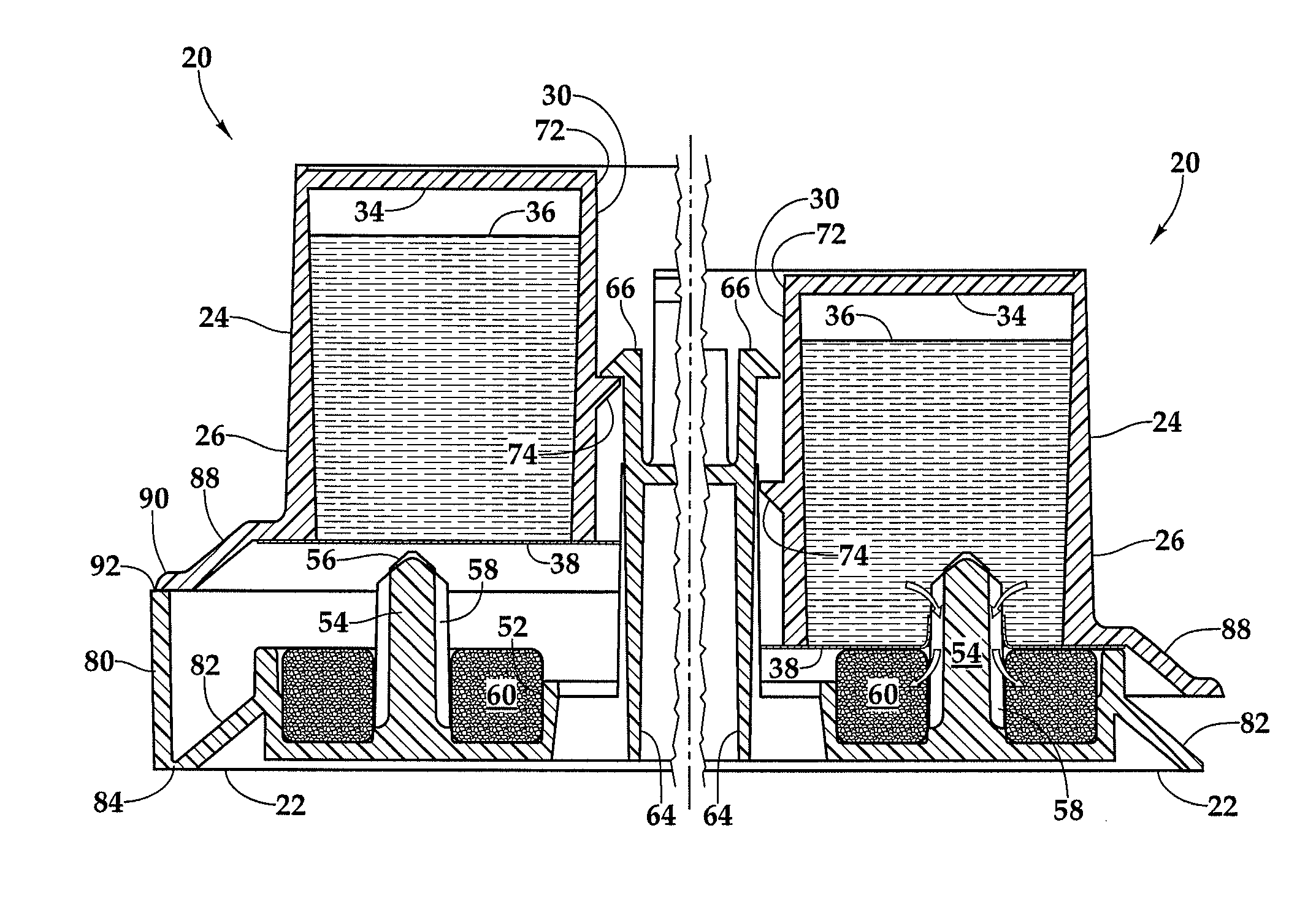
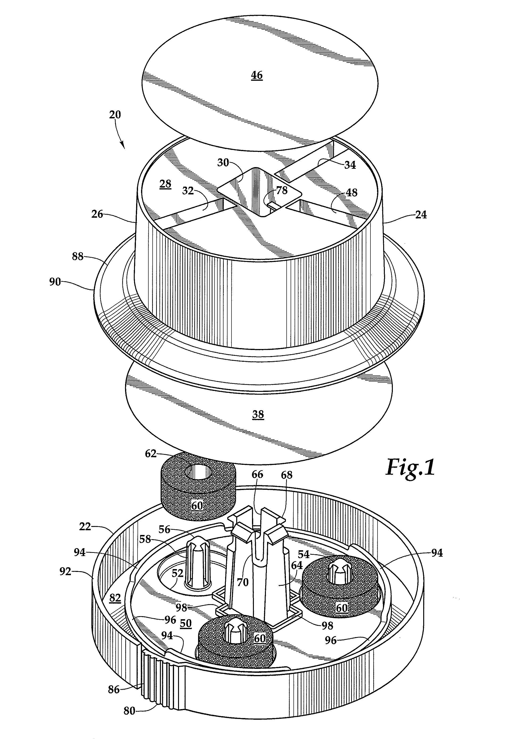
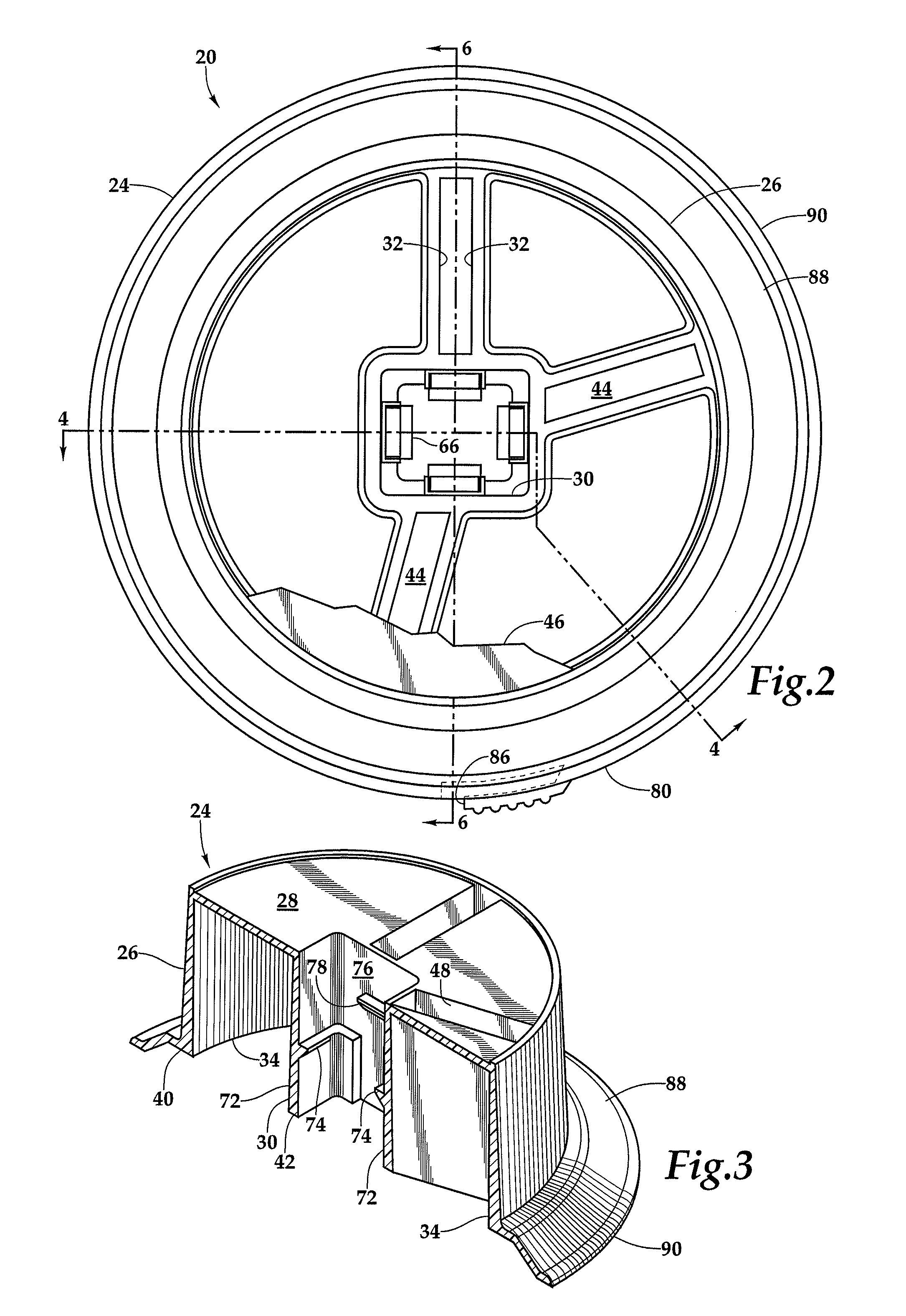
[0024]Referring more particularly to FIGS. 1-15, wherein like numbers indicate similar parts, a toxic insect bait dispenser 20 shown in FIGS. 1-7 has a base 22 with a top 24 which is retained on the base. The base and top 24 may be injection molded plastic parts, formed, for example, of polypropylene. The top has a frustoconical exterior side wall 26. An upper wall 28 extends from the side wall to a central shaft 30 which opens upwardly and downwardly. Double interior walls 32 extend from the side wall 26 to the shaft 30 and divide the top into three compartments 34 which may be filled with insect toxic bait 36, as shown in FIGS. 4-7. The toxic bait within each compartment 34 may have a different composition, in order to target, for example, different varieties of ants, or the same toxic bait may be retained within all the compartments.

[0025]The fluid toxic bait 36 is retained within the compartments 34 by a foil disk barrier 38, shown in FIG. 1. The foil disk 38 is adhered to the t...


PUM


Abstract

An insect toxic bait dispenser has a top with multiple downwardly opening compartments in which toxic bait fluids may be retained by an underlying foil barrier. The top is supported on a base with posts positioned beneath the barrier. Base prongs extend into a top shaft with ledges at different heights, preventing part separation when the barrier is intact above the posts, and, when the top is closed on the base, piercing the foil seal and dispensing liquids into fluid retaining members held in base pockets. To use, a peripheral tear strip is removed from the base, permitting the top to descend on the base causing the posts to puncture the seal, compressing the fluid retaining members against the barrier to receive and dispense toxic bait liquid while retarding the rate of liquid evaporation. The top may be hinged to the base, or urged downwardly by a threaded cap.

Description

CROSS REFERENCES TO RELATED APPLICATIONS[0001]Not applicable.STATEMENT AS TO RIGHTS TO INVENTIONS MADE UNDER FEDERALLY SPONSORED RESEARCH AND DEVELOPMENT[0002]Not applicable.BACKGROUND OF THE INVENTION[0003]The present invention relates to containers for dispensing toxic insect bait liquids.[0004]Certain insect pests will exhibit variations in dietary preferences, making it difficult to address particular insect infestations with a single toxic bait. When this is the case, for example with ants, bait dispensers may be configured to simultaneously dispense more than one variety of bait. Oftentimes the bait is presented in liquid form, yet it is desirable that a bait dispenser be capable of an extended term of use between the times of replenishment. It is therefore desirable that a dispenser of liquid bait offer mechanisms for making the toxic liquid bait readily available to the targeted insect species while retarding as much as possible the evaporation of the liquid.SUMMARY OF THE I...

Claims


Application Information

Patent Timeline
Patent Type & Authority Patents(United States)
IPC IPC(8): A01M1/20A01M25/00A01M1/02
CPCA01M1/02A01M1/2005A01M1/2011A01M1/20
Inventor ZEAMER, PAUL R.WALSH, JAMES R.
Owner MCLAUGHLIN GORMLEY KING CO INC
Why Eureka
Try Eureka