Spectrometric synthetic aperture radar

a synthetic aperture radar and synthetic aperture technology, applied in the direction of non-resonant long antennas, instruments, using reradiation, etc., can solve the problems of loss of target information and undesirable loss of spectral discrimination, and achieve the effects of reducing fuel burn, reducing fuel consumption, and increasing electrical efficiency

Active Publication Date: 2015-04-28
OBERMEYER HENRY K
View PDF31 Cites 15 Cited by
  • Summary
  • Abstract
  • Description
  • Claims
  • Application Information

AI Technical Summary

Benefits of technology

[0014]It is an object of this invention to provide a synthetic aperture radar with decade-plus bandwidth over the VHF and UHF bands that have been proven effective for foliage penetration and ground penetration in a form factor that is compatible with single engine manned aircraft or equivalently sized UAVs. The decade-plus bandwidth serves several objectives. Firstly, it provides fine range resolution. Secondly, it may be selected to bracket the entire impulse response spectrum of selected targets of interest enabling spectral, as well as polarimetric, target identification. These two objectives may, for some applications, be served simultaneously by creating a high resolution radio frequency panchromatic scene onto which may be mapped at slightly lesser resolution spectral target response.

Problems solved by technology

Conventional utilization of all available waveform data to exclusively support range resolution results in loss of spectral discrimination of targets.
Accordingly, coherent addition, without phase correction, of complex signals from disparate wavelengths may result in undesirable loss of target information.

Method used


Image

  • Spectrometric synthetic aperture radar
  • Spectrometric synthetic aperture radar
  • Spectrometric synthetic aperture radar

Examples


Embodiment Construction

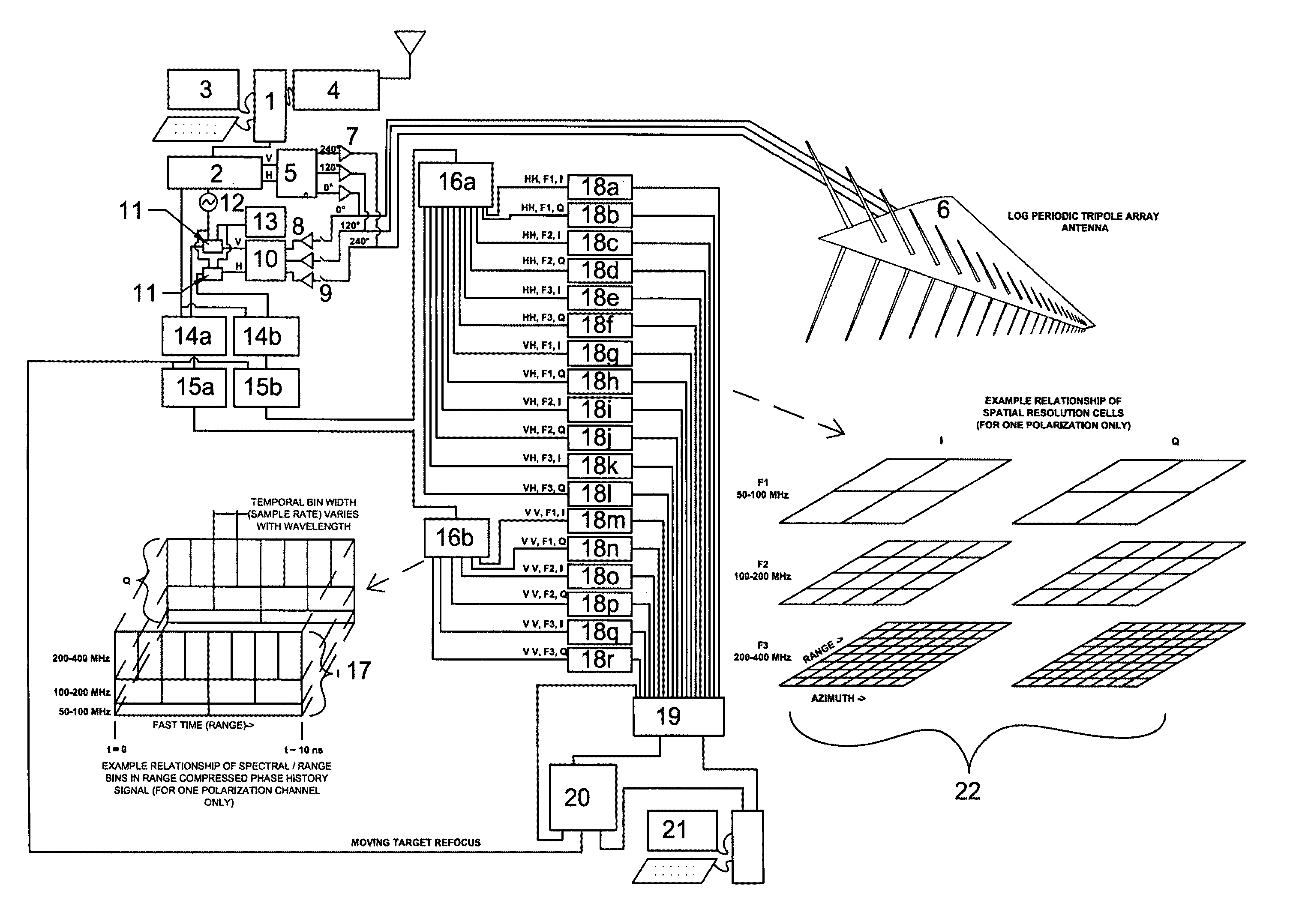
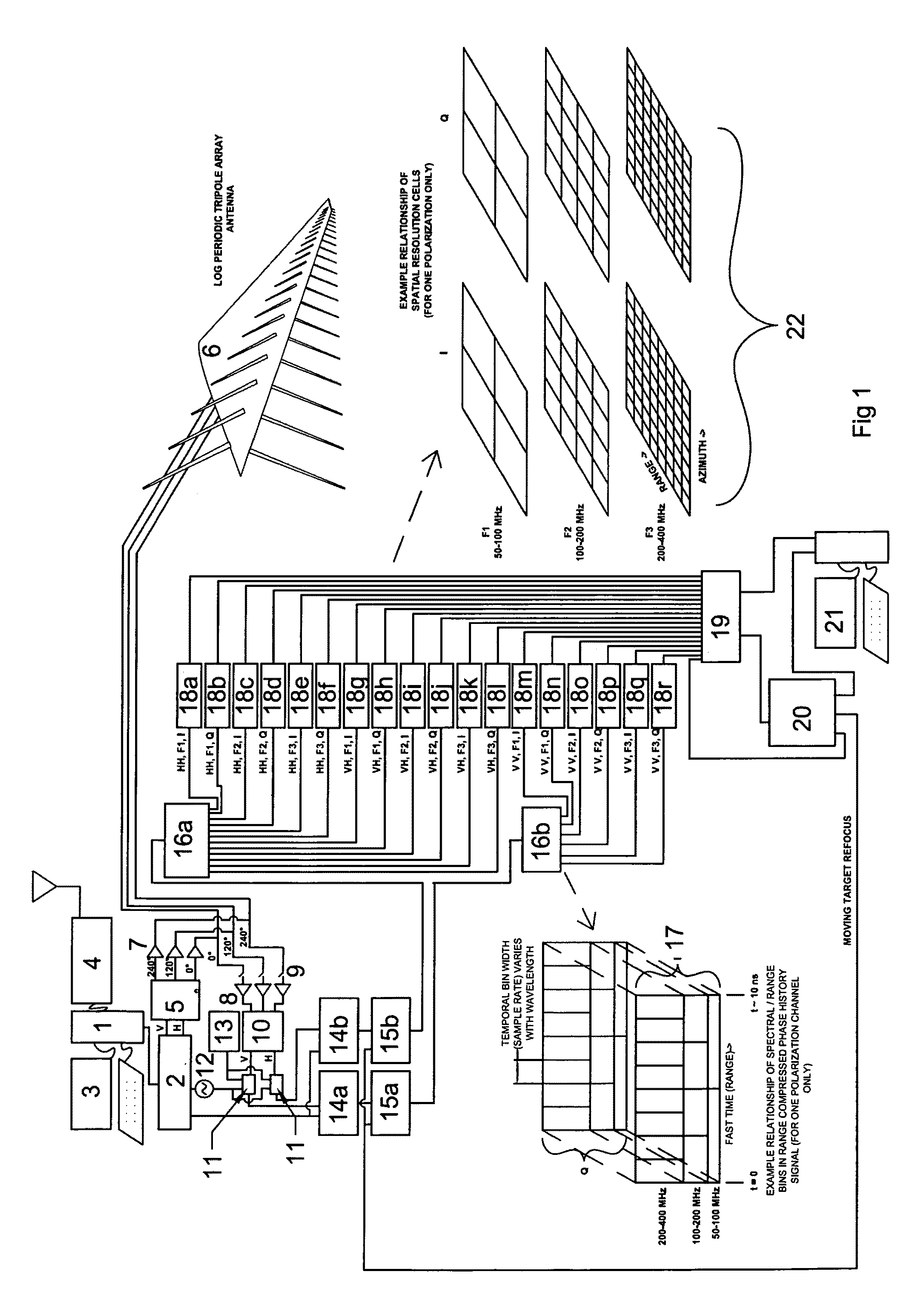
[0074]Referring to FIG. 1, a generalized schematic diagram for a spectrometric synthetic aperture radar system in accordance with the present invention is depicted. Controller computer 1 controls digital wave form generator 2 in response to radar collect parameters from operator interface 3 and interference and jamming receiver 4. Digital waveform generator 2 generates signals corresponding to the vertically and horizontally polarized signals, chirps for example, to be transmitted. Ortho to vector converter 5 translates the vertical and horizontal input signals into 0 degree, 120 degree, and 240 degree output signals needed to reproduce, as radio wave transmissions from the log periodic tripole array antenna (LPTA) 6, the desired polarization. Power amplifiers 7 (shown for simplicity as single stages of amplification) increase the signal level to the level desired for radar transmission. The received signals are fed to low noise amplifiers (LNAs) 8 through transmit-receive (T / R) swi...


PUM


Abstract

This invention relates to improved ultra-wideband synthetic aperture radar and inverse synthetic aperture radar, capable of simultaneously and independently imaging a plurality of spectral and polarimetric channels covering multiple radio frequency octaves. Advances in technologies relating to signal processing, graphical user interfaces, color representations of multi-spectral radar images, low aerodynamic drag polarimetric SAR antenna systems, and synthetic aperture radar aircraft platforms are some of the advancements disclosed herein.

Description

[0001]This application claims the benefit of U.S. Provisional Application No. 60 / 874,397 filed Nov. 30, 2006 which is hereby incorporated by reference. United States Provisional Application entitled “Airborne Ultra-wideband Synthetic Aperture Radar” filed Nov. 30, 2007 is also hereby incorporated by reference.BACKGROUND OF THE INVENTION[0002]1. Field of Invention[0003]The present invention relates to improved ultra-wideband synthetic aperture radar and aircraft antennas therefore. The exploitation of the radio frequency spectral content including, for example, VHF / UHF bandwidths of a decade or more, of synthetic aperture generated images using airborne platforms of limited size, is disclosed. Antenna polarization agility may be provided by a log periodic tripole array that provides low aerodynamic drag, robust aerodynamic stability, and uniform gain over its bandwidth without the need for a radome.[0004]2. Description of Related Art[0005]Airborne synthetic aperture radar has histori...

Claims


Application Information

Patent Timeline
Patent Type & Authority Patents(United States)
IPC IPC(8): G01S13/90H01Q1/28H01Q11/10
CPCG01S13/90H01Q1/28H01Q11/10G01S13/9023G01S2013/9064G01S2013/9076G01S13/9029G01S13/9064G01S13/9076
Inventor OBERMEYER, HENRY K.
Owner OBERMEYER HENRY K
Why Eureka
Try Eureka