
Computer pointing device

a technology of pointing device and input, which is applied in the direction of instruments, electric digital data processing, cathode-ray tube indicators, etc., can solve the problems of small accuracy, device only able to perform convex movements or parallel movements to their base, and the need for a flat pad on which the ball comprising the steering element moves

Inactive Publication Date: 2010-08-17
DENCO LOGIC
View PDF11 Cites 2 Cited by
  • Summary
  • Abstract
  • Description
  • Claims
  • Application Information

AI Technical Summary

Benefits of technology

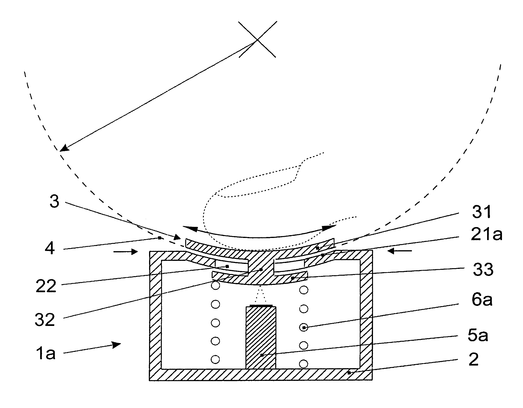
"The present invention is a computer input pointing device with a steering element that is supported by a bearing in the casing. The center of the bearing is positioned above the largest horizontal secant surface of the steering element. This design allows for more precise and comfortable movements of the user's hand or finger in relation to the device. The movement of the steering element is concave to the device, which makes it more ergonomic and less tiring in practical use. The device can be used in portable computers and is more comfortable to use. The bearing can be a spherical shape or composed of sections bent in a spherical way. The steering element can be designed with a hollow space inside and a hole in the lower surface, which enhances its ergonomics. The steering element can also have a dome part for the user's hand or finger, which makes it more comfortable and precise in use. The movement of the steering element can be detected with a micro-camera or a light emitter and optical sensor. The device can also have repositioning elements that enable the steering element to recover."

Problems solved by technology

Nevertheless, the need for a flat pad on which the ball comprising the steering element moves limits its application mainly to stationary computers.
Quite often though, in practical use their accuracy is small, because the movement of the steering element is performed on a small surface, it is not precise and / or not ergonomic.
Such devices can only perform convex movements or the movements which are parallel to their base.
Due to the character of such movement, in vast majority of existing solutions it is necessary to apply arm, forearm and hand muscles to displace the steering element; hence prolonged using of such devices is tiresome.
Considering the fact that the working area of computer monitor—so called desktop—is usually positioned vertically, beginner computer users have problem how to move the cursor towards the top of the screen with the use of standard input pointing devices.
Other pointing devices such as trackpoint, touchpad or trackball do not allow to control cursor movements according to the expectations of beginner computer users so they do not solve that problem either.

Method used


Image

  • Computer pointing device
  • Computer pointing device
  • Computer pointing device

Examples


Embodiment Construction

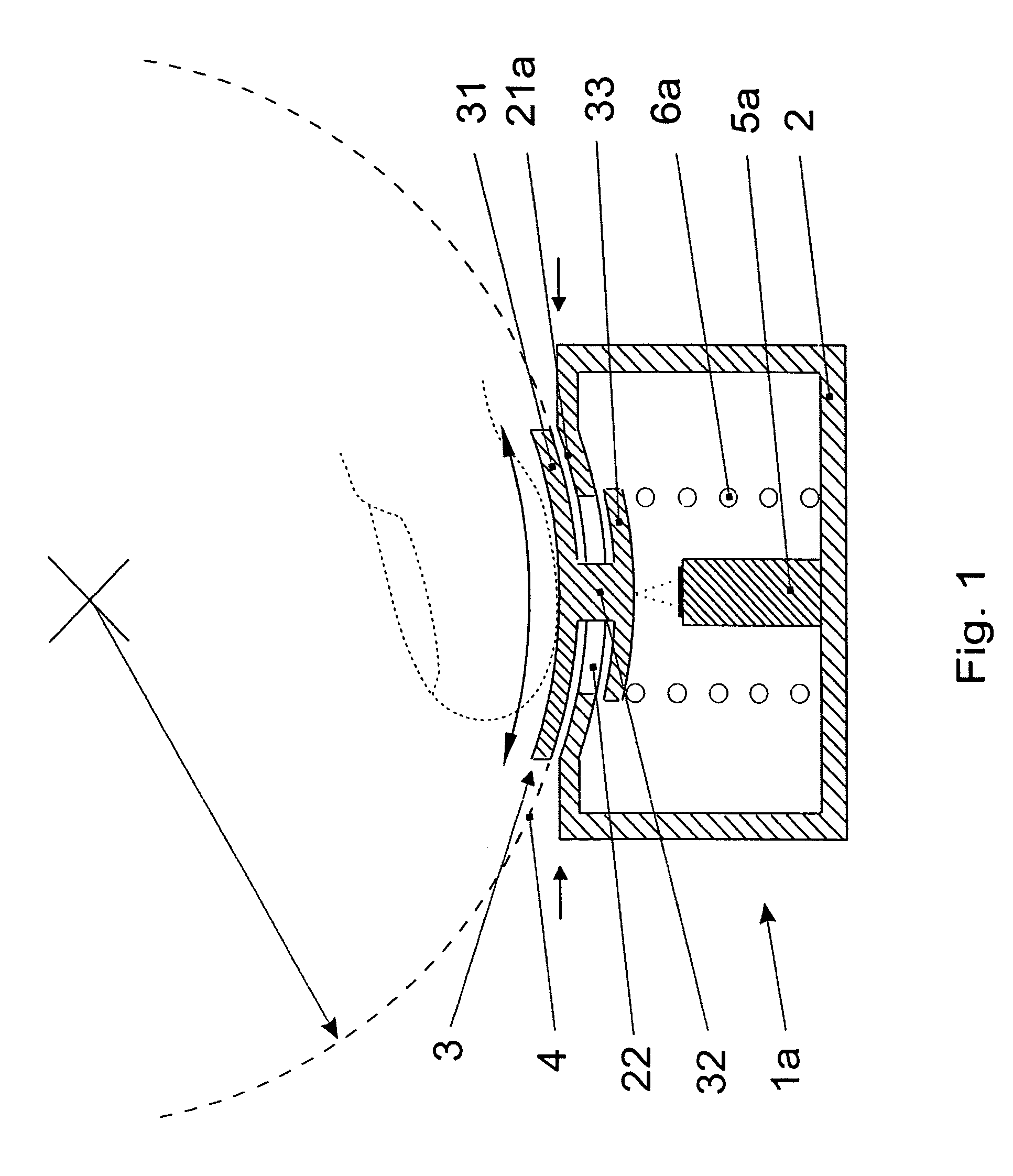
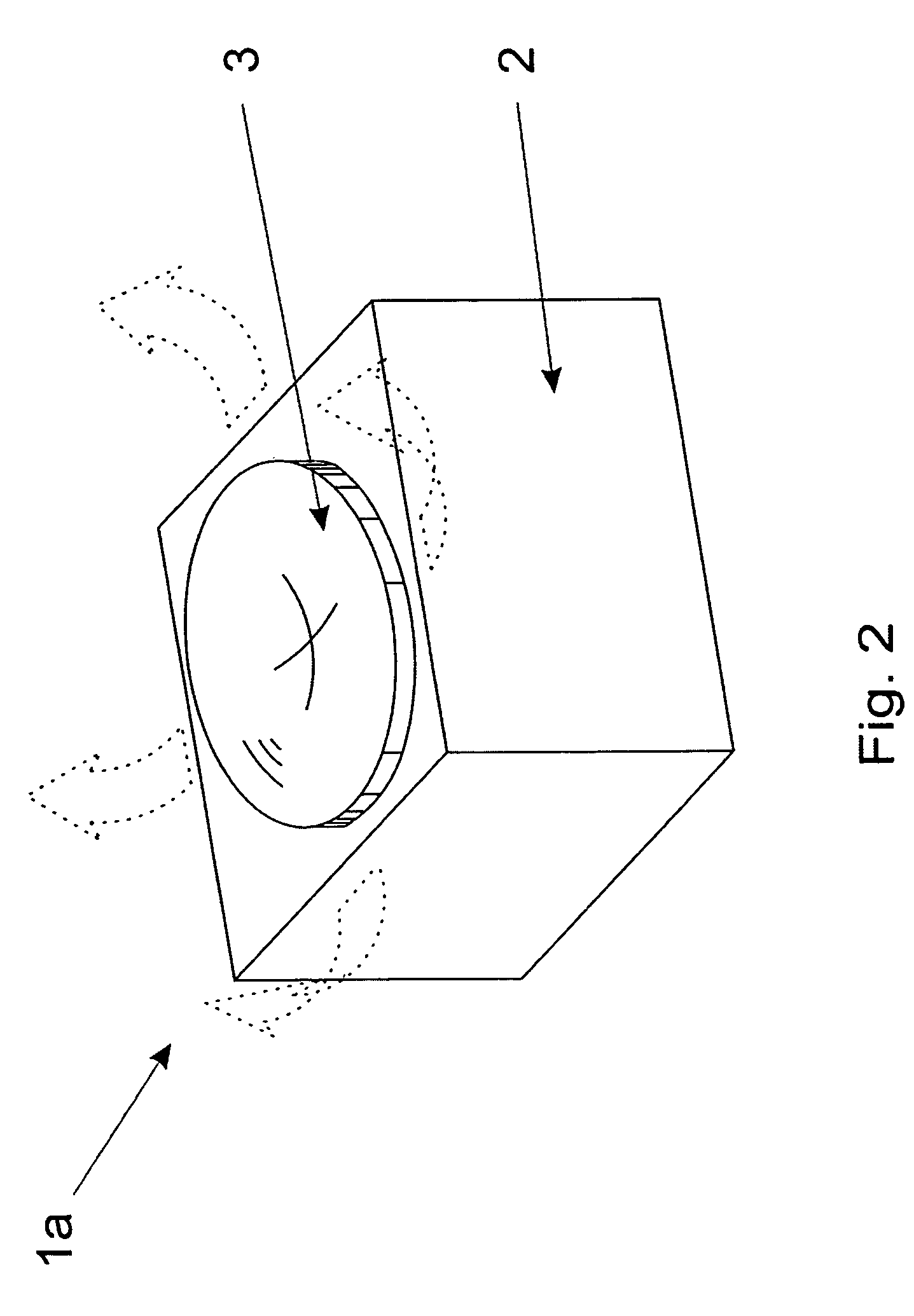
[0048]The computer input pointing device 1a shown in diagrams FIG. 1 and FIG. 2 comprises the casing 2 and the movable steering element. The upper part of the casing is concave and forms a spherical bearing 21a for the steering element 3. Moreover, there is a square hole 22 in the bearing 21a. The steering element 3 has been designed as one part composed of three functional elements: upper part 31, whose lower surface has a shape of a sector of the sphere respective to the curve of casing's 2 bearing 21, whereas the upper surface has an ergonomic shape adjusted to schematically displayed user's finger; connecting element 32, leading through the hole 22; and protective lower end 33 which prevents the steering element from falling out of the casing.

[0049]The steering element may be relocated on the casing's 2 bearing 21; such movement is performed on a sector of the sphere 4 marked with a dashed line as a circle in the diagram FIG. 1, and is registered with the use of schematically sh...


PUM


Abstract

The Invention relates to a computer input pointing device which comprises its casing (2), an upper movable steering element (3), steering element's movement detector (5a), and the system transmitting information about such movement to the computer. Such device is applicable especially in portable computers. To enhance ergonomics and the precision of steering element (3) movement as well as the comfort of its control, the steering element is supported by a bearing (21a) in the casing (2), with the possibility of two dimensional spherical movement, while the center of the spherical surface (4) defined by the movement of the steering element (3) in relation to the bearing is situated above the largest horizontal secant surface of the steering element (3).

Description

FIELD OF THE INVENTION[0001]The Invention relates to a computer input pointing device comprising its casing, an upper movable steering element, steering element's movement detector, and the system transmitting information about such movement to the computer. Such devices are applied to control the movement of the cursor on the computer screen while at work in graphic environment.BACKGROUND OF THE INVENTION[0002]The comfort of an input pointing device usage is determined by the way its steering element is relocated. The device should enable its user to make clear and free movements of the steering element by his / her hand or finger. Such movement is scanned by detecting elements—mechanical or optical ones and transformed by a relevant electronic system into an input stream of computer data. Moreover such device should be universal and particularly sensitive to differences in the dynamics of steering element's movements. It is essential that such device be as precise while moved slowly...

Claims


Application Information

Patent Timeline
Patent Type & Authority Patents(United States)
IPC IPC(8): G09G5/08G06F3/03G06F3/0338G06F3/042G09G5/00
CPCG06F3/0312G06F3/0317G06F3/0338
Inventor KOSU, PATRYCJUSZ
Owner DENCO LOGIC
Learn More