Clutch actuator, engine unit, and saddle type vehicle

a technology of clutch actuator and engine, which is applied in the direction of interlocking clutches, cycle equipment, and gearing, etc., can solve the problems of increasing weight and increasing the size of the actuator, and achieve the effects of increasing weight, reducing responsiveness, and increasing structur

Active Publication Date: 2009-12-22
YAMAHA MOTOR CO LTD +1
View PDF66 Cites 3 Cited by
  • Summary
  • Abstract
  • Description
  • Claims
  • Application Information

AI Technical Summary

Benefits of technology

[0009]However, because the shaft member is thickened, the attachment radius of the output rod (i.e., the distance from the center of the shaft member to the point where the output rod is attached) is enlarged, whereby the actuator becomes bigger. Further, because the attachment radius of the output rod is enlarged, the rotation angle that the crank shaft is required to rotate in order to move the output rod the same stroke is reduced, and thus the rotation angle of the worm wheel is smaller. Accordingly, when the disengagement-engagement operation of the clutch is performed, the necessary motor rotation angle is smaller.
[0010]However, when the disengagement-engagement operation of the clutch is performed, in order to accurately control operation of the worm wheel, it is necessary to ensure, to some extent, a large maximum rotation angle of the motor. Thus, a design is sought in which the diameter of the worm wheel is larger, and the reduction ratio between the worm shaft and the worm wheel is larger. However, if the diameter of the worm wheel is made larger, the actuator becomes larger and the weight is also increased. Further, if the reduction gear ratio is enlarged, the operation of the output rod does not rapidly follow the rotation of the motor, and thus the clutch engagement-disengagement operation becomes less responsive.
[0011]As a result of the above, the conventional clutch actuator has a larger structure, increased weight, and decreased responsiveness. Further, this type of clutch actuator is less suitable for a saddle type vehicle like a motorcycle.
[0012]Thus, one aspect of an embodiment of the invention comprises a clutch actuator, an engine unit including the clutch actuator, and a saddle type vehicle including the engine unit that can limit an increase in structure size and weight while improving the responsiveness of the clutch disengagement-engagement operation.
[0014]Because the first bearing is provided between the worm wheel and the crank arm, the crank shaft member of the crank shaft is reliably supported by the first bearing. This support, in part, enables the crank shaft member to be made thinner. Therefore, the attachment radius of the output rod can be decreased. Because the attachment radius of the output rod is smaller, it is possible to increase the rotation angle required of the crank shaft member to move the output rod the same stroke. As a result, the rotation angle of the worm wheel can be increased, thereby allowing the diameter of the worm wheel to be reduced, and the size and weight increase of the actuator can be limited. Further, because the diameter of the worm wheel is smaller, the reduction gear ratio between the worm shaft and the worm wheel can be reduced. Accordingly, the movement of the output rod follows the rotation of the motor rapidly, and the responsiveness of the clutch disengagement-engagement operation can be improved.

Problems solved by technology

However, if the diameter of the worm wheel is made larger, the actuator becomes larger and the weight is also increased.

Method used


Image

  • Clutch actuator, engine unit, and saddle type vehicle
  • Clutch actuator, engine unit, and saddle type vehicle
  • Clutch actuator, engine unit, and saddle type vehicle

Examples


Embodiment Construction

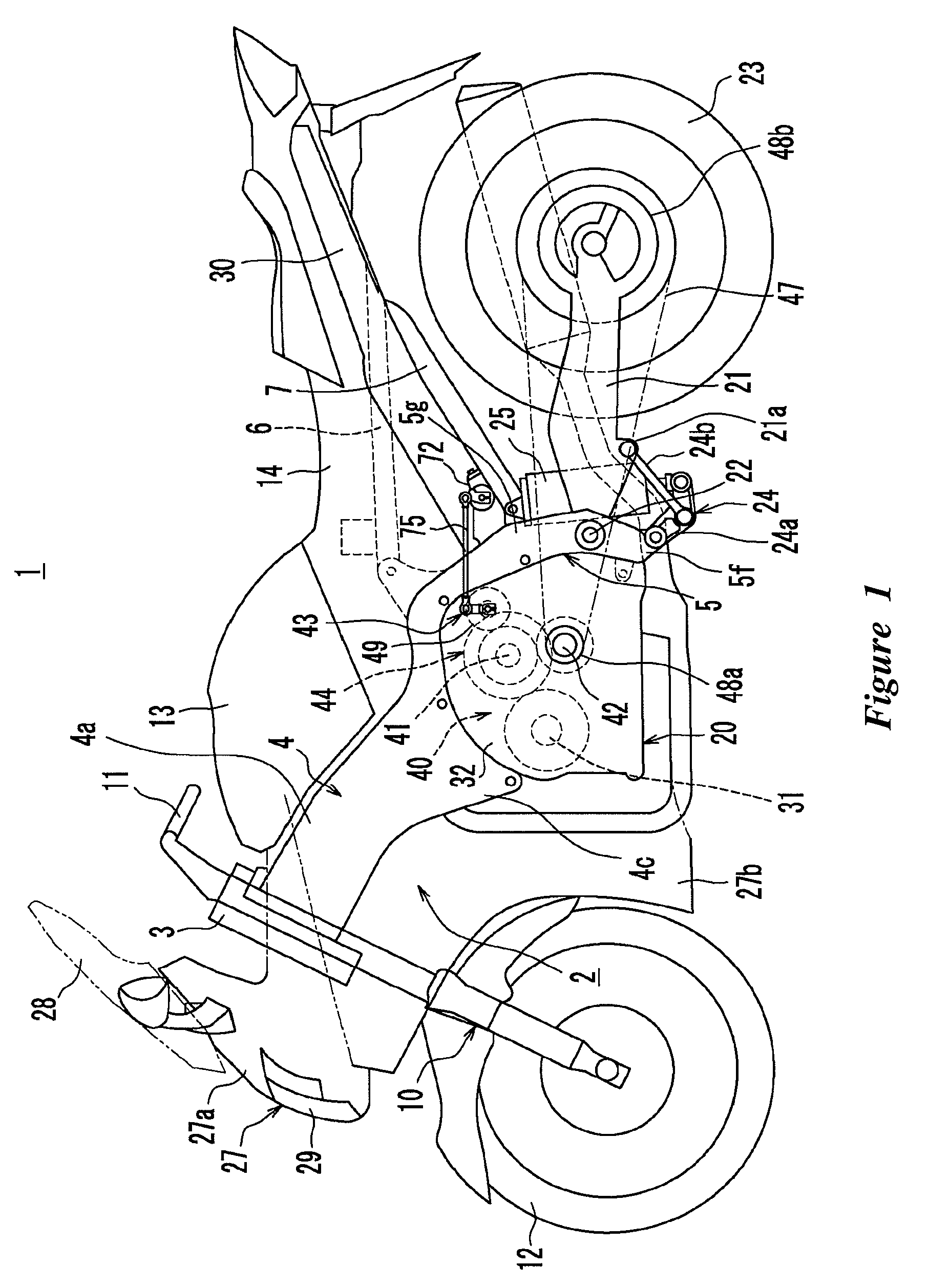
[0034]FIG. 1 is a side view of a motorcycle 1 that is arranged and configured in accordance with certain features, aspects and advantages of an embodiment of the present invention. As can be seen from FIG. 1, the motorcycle 1 comprises a head tube 3 and a body frame 2. The body frame 2 comprises a main frame 4 that extends rearward from the head tube 3 and a rear arm bracket 5 that extends downward from a rear section of the main frame 4. The main frame 4 has two frame sections 4a that extend to the left and right in a rearward direction from the head tube 3 (only one of these is shown in FIG. 1). A rear section of the frame section 4a is connected to the downwardly-extending rear arm bracket 5.

[0035]A front fork 10 is pivotably supported by the head tube 3. A steering handlebar 11 is provided at an upper end of the front fork 10 and a front wheel 12 is provided at a lower end of the front fork 10. In the illustrated configuration, a fuel tank 13 is provided in an upper section of t...


PUM


Abstract

A clutch actuator comprises a worm shaft that rotates along with a clutch motor. The worm shaft is meshed with a worm wheel. The worm wheel is fixed to one end of a crank shaft member of a crank shaft separately from a crank arm of the crank shaft. A bearing that supports the crank shaft is provided between the worm wheel and the crank arm.

Description

CROSS-REFERENCE TO RELATED APPLICATIONS[0001]This application claims the priority benefit of Japanese Patent Application No. 2006-114705, which was filed on Apr. 18, 2006 and which is hereby incorporated by reference in its entirety.BACKGROUND OF THE INVENTION[0002]1. Field of the Invention[0003]The present invention generally relates to a clutch actuator that disengages and engages a clutch. More particularly, the present invention relates to an engine unit that includes such a clutch actuator and a saddle type vehicle, such as a motorcycle, that includes such an engine unit.[0004]2. Description of the Related Art[0005]Conventionally, a system is known that attaches an actuator to a previously existing manual transmission. The actuator is used to automate certain operations such that the system can automate a series of start, stop and shift change operations (clutch disengagement, gear change, and clutch engagement) based on the rider's intention or the state of the vehicle.[0006]A...

Claims


Application Information

Patent Timeline
Patent Type & Authority Patents(United States)
IPC IPC(8): F16D23/12F16D28/00F16H57/023F16H57/037F16H57/038F16H57/039
CPCB62K23/02F16D1/101F16D25/086F16D29/005F16D28/00Y10T74/18792F16D2001/103F16D2048/0254
Inventor KOSUGI, MAKOTOKAZUTA, HISASHI
Owner YAMAHA MOTOR CO LTD
Why Eureka
Try Eureka