Backlight unit comprising a plurality of slits formed on a bottom surface of at least one edge of a bottom cover and liquid crystal display device having the same

a backlight unit and liquid crystal display technology, which is applied in the direction of lighting and heating apparatus, mechanical equipment, instruments, etc., can solve the problems of heavy weight and large size of the crts, affecting the manufacturing of small, light electronic products, and affecting the quality of electronic products. , to achieve the effect of reducing the thermal deformation of the bottom cover

Active Publication Date: 2015-04-28
LG DISPLAY CO LTD
View PDF7 Cites 3 Cited by
  • Summary
  • Abstract
  • Description
  • Claims
  • Application Information

AI Technical Summary

Benefits of technology

[0014]An object of the present embodiments is to provide a backlight unit that is adapted to prevent light leakage and damage of its internal components due to a thermal deformation.
[0015]Another object of the present embodiments is to provide an LCD device that is adapted to improve displaying quality.
[0017]According to one general aspect of the present embodiment, a backlight unit includes: a bottom cover with an opened upper surface; a printed-circuit-board disposed on at least one inner side surface of the bottom cover; a plurality of LEDs loaded on the printed-circuit-board; and a plurality of slits formed on at least one edge of the bottom cover opposite to the printed-circuit-board and configured to reduce thermal deformation of the bottom cover.
[0018]An LCD device according to another general aspect of the present embodiment, includes: a liquid crystal display panel; a bottom cover configured to include an opened upper surface and disposed under the liquid crystal display panel; a printed-circuit-board disposed on at least one inner side surface of the bottom cover; a plurality of LEDs loaded on the printed-circuit-board; and a plurality of slits formed on at least one edge of the bottom cover opposite to the printed-circuit-board and configured to reduce thermal deformation of the bottom cover.

Problems solved by technology

However, the heavy weight and large size of the CRTs have been a major hindrance to the manufacturing of small, light electronic products.
This results from the fact that the bottom cover of a metal material easily expands and contracts with heat.
Due to this, components within the bottom cover can be damaged.
Also, the bent side surface of the bottom cover causes light to be leaked from the edge of the bottom cover, so that brightness of the backlight unit (and the LCD device) is deteriorated.
Consequently, the thermal deformation of the bottom cover can deteriorate displaying quality of the LCD device.

Method used


Image

  • Backlight unit comprising a plurality of slits formed on a bottom surface of at least one edge of a bottom cover and liquid crystal display device having the same
  • Backlight unit comprising a plurality of slits formed on a bottom surface of at least one edge of a bottom cover and liquid crystal display device having the same
  • Backlight unit comprising a plurality of slits formed on a bottom surface of at least one edge of a bottom cover and liquid crystal display device having the same

Examples


Embodiment Construction

[0028]Reference will now be made in detail to the embodiments of the present disclosure, examples of which are illustrated in the accompanying drawings. These embodiments introduced hereinafter are provided as examples in order to convey their spirits to the ordinary skilled person in the art. Therefore, these embodiments might be embodied in a different shape, so are not limited to these embodiments described here. Also, the size and thickness of the device might be expressed to be exaggerated for the sake of convenience in the drawings. Wherever possible, the same reference numbers will be used throughout this disclosure including the drawings to refer to the same or like parts.

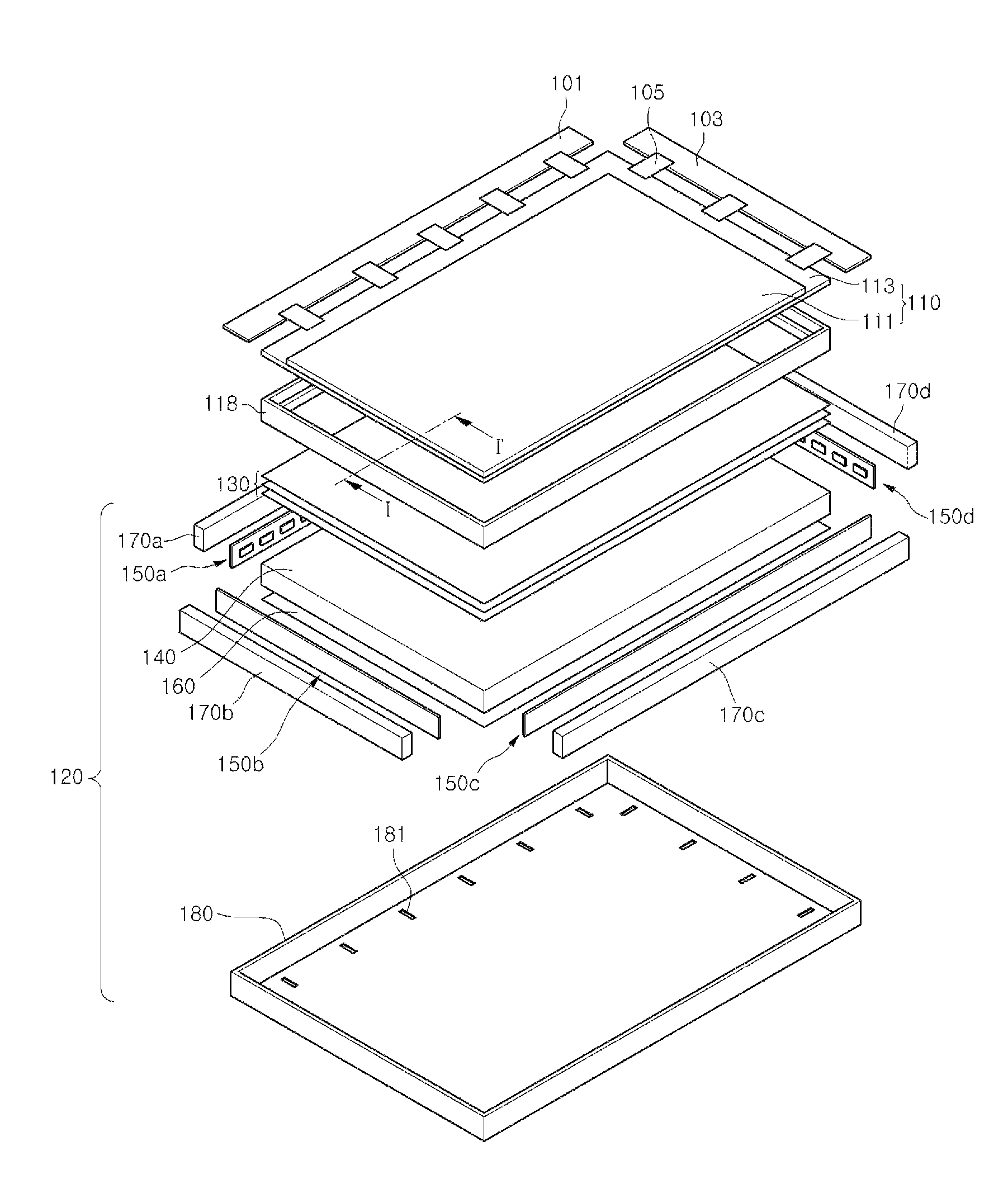
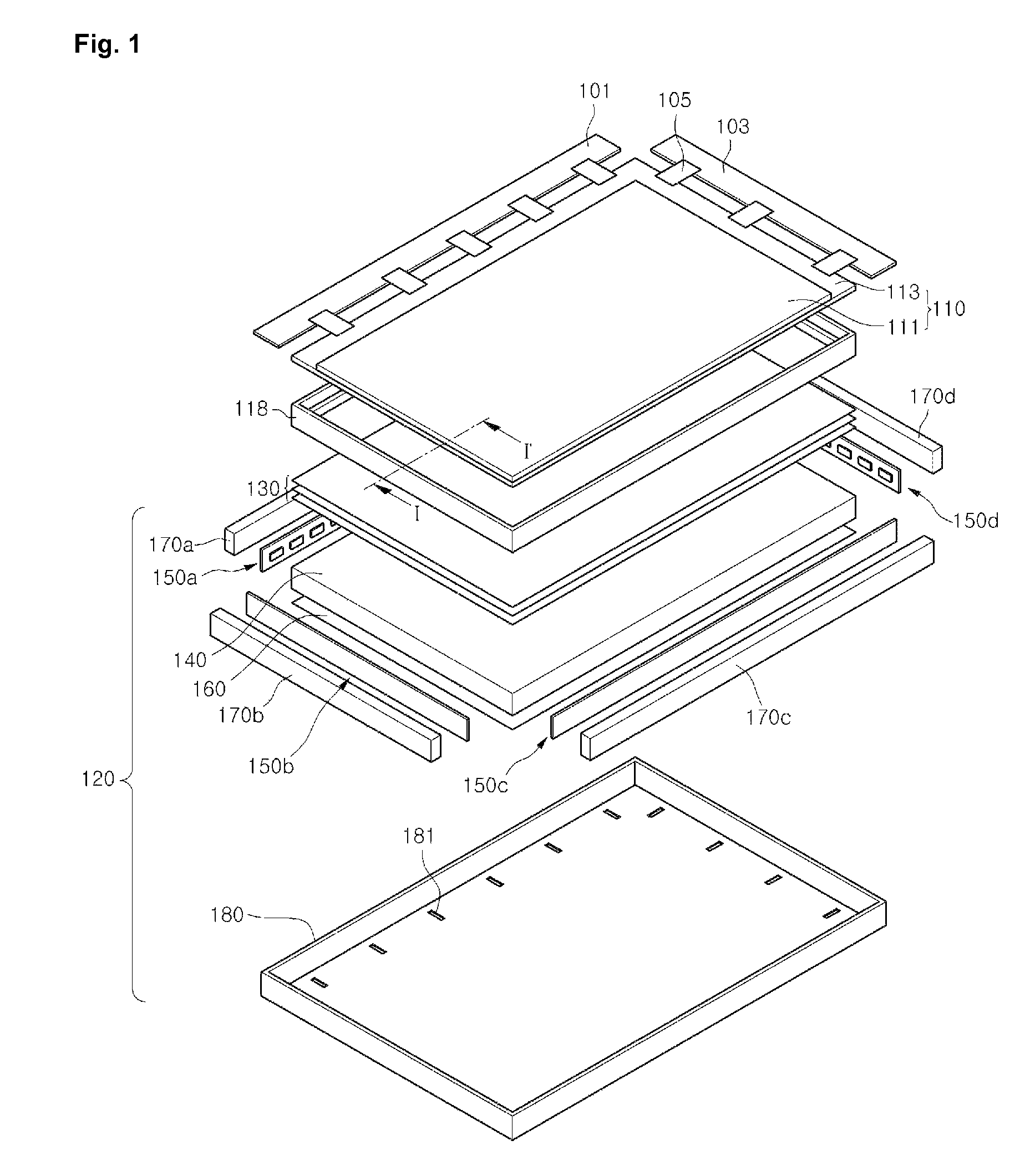
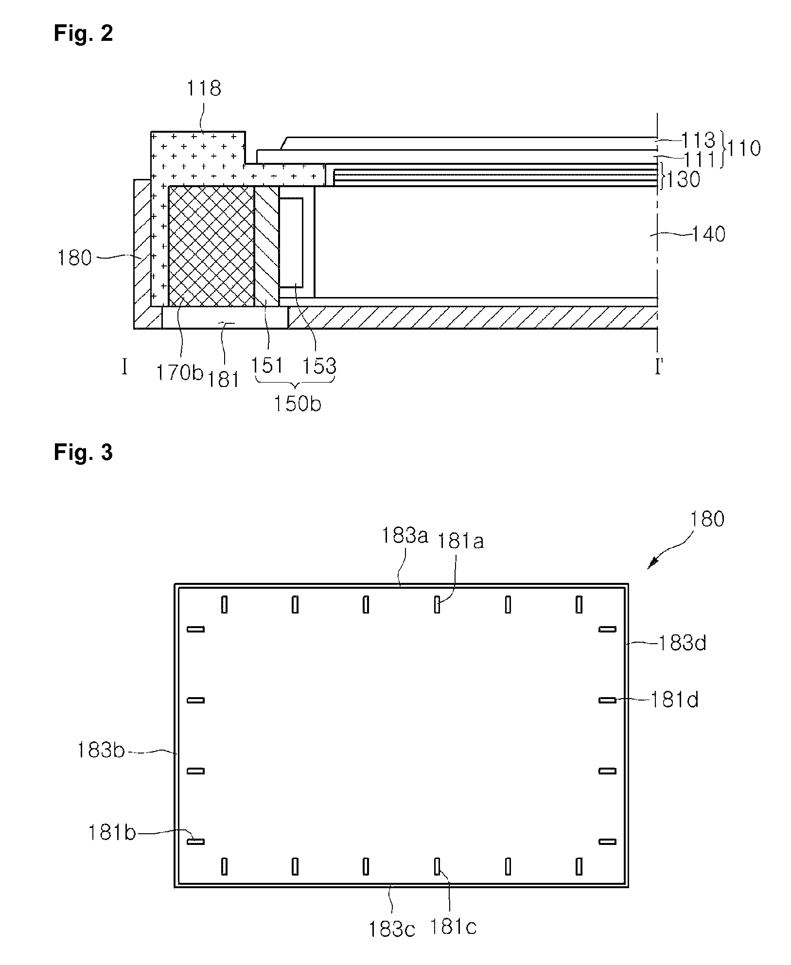
[0029]FIG. 1 is a disassembled perspective view showing an LCD device according to an embodiment of the present disclosure. FIG. 2 is a cross-sectional view showing the LCD device taken along a line I-I′ in FIG. 1. FIG. 3 is a planar view showing a bottom cover according to an embodiment of the present disc...


PUM

PropertyMeasurementUnit
thermal deformationaaaaaaaaaa
longitudeaaaaaaaaaa
shapeaaaaaaaaaa

Abstract

A backlight unit adapted to prevent light leakage and damage of its internal components due to a thermal deformation is disclosed.The backlight unit includes: a bottom cover with an opened upper surface; a printed-circuit-board disposed on at least one inner side surface of the bottom cover; a plurality of LEDs loaded on the printed-circuit-board; and a plurality of slits formed on at least one edge of the bottom cover opposite to the printed-circuit-board and configured to reduce thermal deformation of the bottom cover.

Description

CROSS-REFERENCE TO RELATED APPLICATION[0001]This application claims priority under 35 U.S.C. 119 to Korean Patent Application No. 10-2009-0072060, filed on Aug. 5, 2009, which is hereby incorporated by reference in its entirety.BACKGROUND[0002]1. Field of the Disclosure[0003]This disclosure relates to a backlight unit, and more particularly to a backlight unit adapted to prevent light leakage caused by a thermal deformation, and a liquid crystal display (LCD) device with the same.[0004]2. Description of the Related Art[0005]Cathode ray tubes (CRTs), which correspond to one of widely used display devices, are mainly used as monitors for TVs, measuring apparatuses, or information terminals. However, the heavy weight and large size of the CRTs have been a major hindrance to the manufacturing of small, light electronic products.[0006]To address this matter, LCD devices are gradually being used in a wide range of applications due to their advantages such as lightness, thinness, and low p...

Claims


Application Information

Patent Timeline
Patent Type & Authority Patents(United States)
IPC IPC(8): G02F1/1335G09F13/04F21V7/04F21V8/00G02F1/1333
CPCG02B6/0068G02B6/0085G02F1/133308G02B6/0073G02F1/133615G02F2001/133314G02F2001/133628G02F2201/54G02F1/133314G02F1/133628G02F1/1333G02F1/1335G02F1/1345
Inventor PARK, HEONG SOODAN, KYUNG SIK
Owner LG DISPLAY CO LTD
Why Eureka
Try Eureka