
Embedded system using image coding method

a technology of embedded systems and image coding, applied in the field of embedded systems using image coding methods, can solve the problems of inability to efficiently perform dct in embedded systems with a low processing speed and a small-capacity memory, inability to compress images, and inability to operate personal computers, etc., to achieve easy compression of images, low memory usage, and simple comparison

Inactive Publication Date: 2015-05-05
NAT CHIAO TUNG UNIV
View PDF5 Cites 0 Cited by
  • Summary
  • Abstract
  • Description
  • Claims
  • Application Information

AI Technical Summary

Benefits of technology

[0007]It is an objective of the present invention to provide an image coding method that combines the schemes of Block-Edge Detection (BED) and Low-Complexity and Low-Memory Entropy Coder (LLEC) to achieve high compression ratio (CR) and low distortion.
[0008]Another objective of the present invention is to provide an embedded system that applies the aforesaid image coding method to achieve low-complexity operation and high memory usage during a coding process performed on the image.
[0012]BED is an algorithm intended for simple comparison, whereas LLEC is an algorithm which features low memory usage. Hence, the embedded system compresses the image easily, using BED and LLEC.

Problems solved by technology

Although the image compression standards achieve high-quality image compression by means of DCT, DCT has a limitation, that is, image compression cannot be accomplished by means of DCT without personal computers operating at a high processing speed and having a large-capacity memory.
However, unlike the personal computers, embedded systems with a low processing speed and a small-capacity memory are unable to perform DCT efficiently.
Hence, with the embedded systems being subject to hardware requirements, the embedded systems are unable to compress the image efficiently.

Method used


Image

  • Embedded system using image coding method
  • Embedded system using image coding method
  • Embedded system using image coding method

Examples


Embodiment Construction

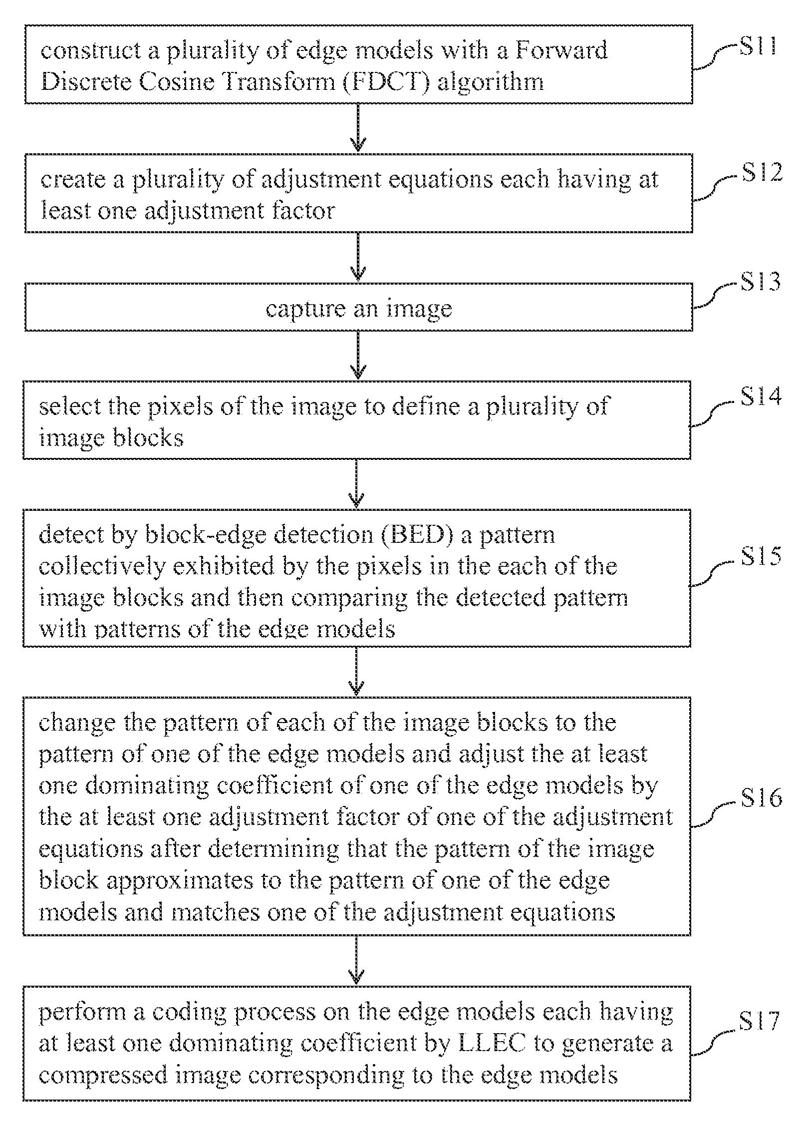
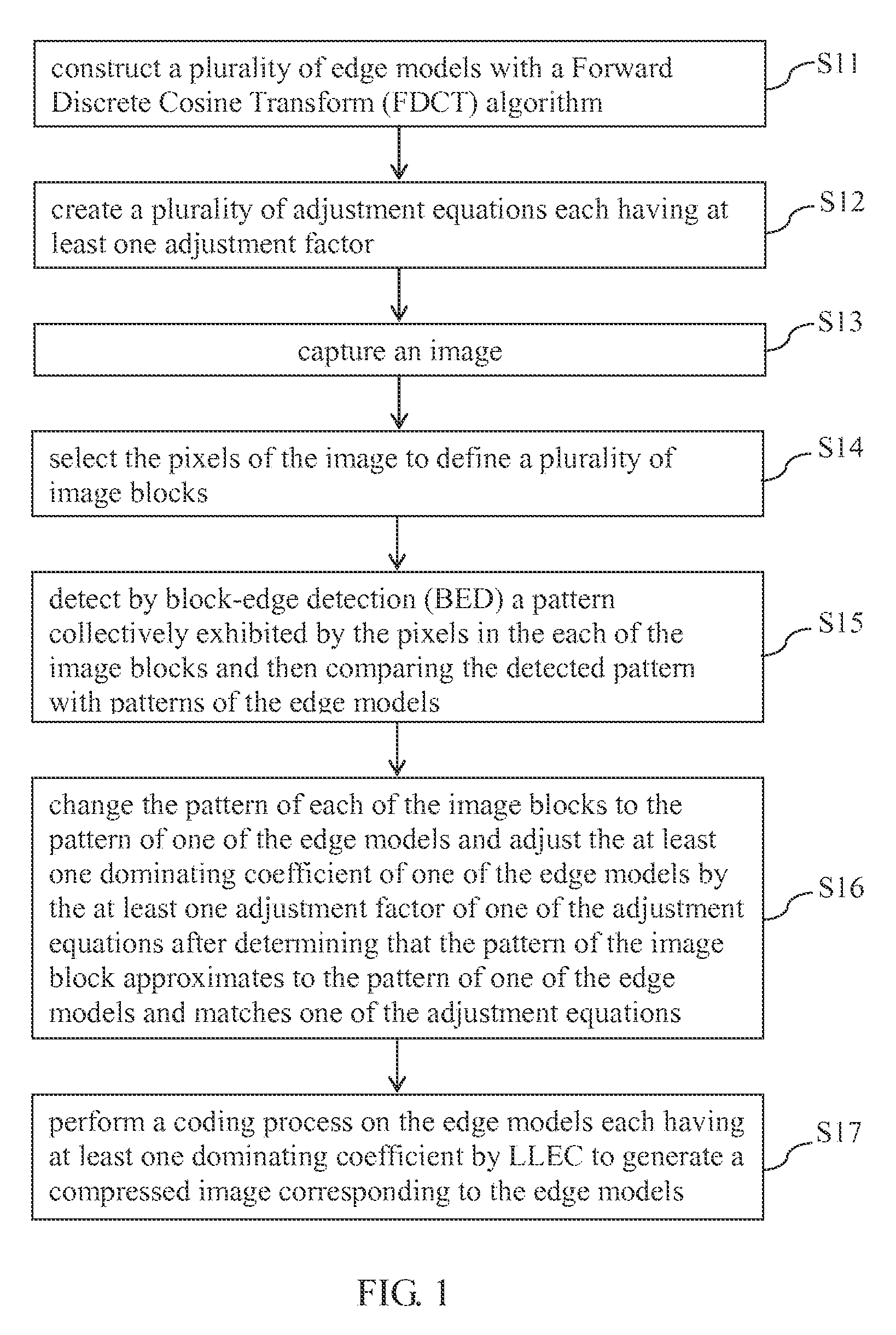
[0018]Referring to FIG. 1, there is shown a block diagram of the process flow of an image coding method according to an embodiment of the present invention.

[0019]The process flow of the image coding method starts with step S11 in which a plurality of edge models is constructed with a Forward Discrete Cosine Transform (FDCT) algorithm. Each of the edge models matches at least one dominating coefficient. The dominating coefficients include positive integers and zero.

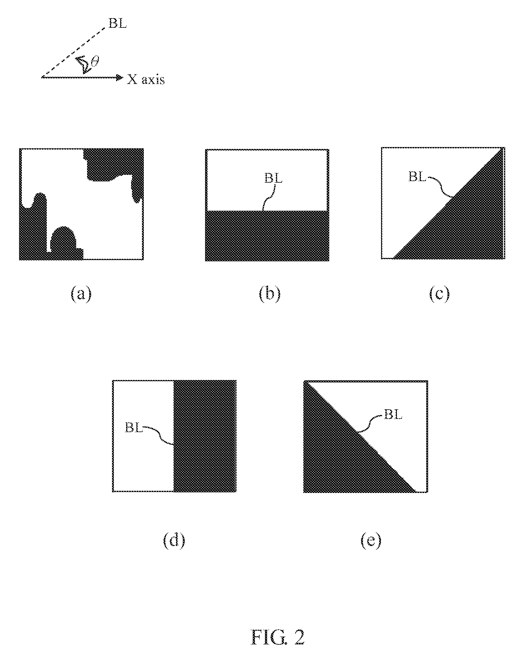
[0020]Referring to FIGS. 2(a)-(e), for example, the edge models are each defined with a boundary line BL between a black region and a white region, and the included angle θ between the boundary line BL and the x-axis direction. FIG. 2(a) illustrates a no-edge model (hereinafter referred to as the “first edge model”.) FIG. 2(b) illustrates a 0°-edge model (hereinafter referred to as the “second edge model”.) FIG. 2(c) illustrates a 45°-edge model (hereinafter referred to as the “third edge model”.) FIG. 2(d) illustrates a 9...


PUM


Abstract

An image coding method including constructing a plurality of edge models with a Forward Discrete Cosine Transform (FDCT) algorithm; creating adjustment equations each matching one of the edge models; capturing an image comprising pixels; selecting the pixels of the image to define image blocks; detecting by block-edge detection (BED) a pattern collectively exhibited by the pixels in the each of the image blocks and then comparing the detected pattern with patterns of the edge models; changing the patterns of the image blocks to the patterns of the edge models and adjusting the dominating coefficient by the adjustment factor after determining that the patterns of the image blocks approximate to the patterns of the edge models; and performing a coding process on the edge models by LLEC to generate a compressed image corresponding to the edge models. An embedded system is applicable to the image coding method.

Description

CROSS-REFERENCE TO RELATED APPLICATION[0001]This non-provisional application claims priority under 35 U.S.C. §119(a) on Patent Application No(s). 102103279 filed in Taiwan, R.O.C. on Jan. 29, 2013, the entire contents of which are hereby incorporated by reference.FIELD OF THE INVENTION[0002]The present invention relates to image coding methods and systems using the same, and more particularly, to an image coding method which combines the schemes of Block-Edge Detection (BED) and Low-Complexity and Low-Memory Entropy Coder (LLEC), and an embedded system using the image coding method.BACKGROUND OF THE INVENTION[0003]Transform coding plays an important role in conventional image compression. The purpose of transform coding is to reduce redundant data created during the image compression process. At present, the transform coding entails performing Discrete Cosine Transform (DCT). For instance, image compression standards, such as JPEG, JPEG2000, MPEG-1 / 2, MPEG4, H.263, and H.264 / AVC, ap...

Claims


Application Information

Patent Timeline
Patent Type & Authority Patents(United States)
IPC IPC(8): G06K9/46G06V10/44H04N19/12H04N19/14H04N19/176
CPCG06K9/4642H04N19/176H04N19/12H04N19/14G06K9/4604G06V10/44
Inventor WU, BING-FEICHEN, YEN-LINHUANG, HAO-YU
Owner NAT CHIAO TUNG UNIV
Learn More