Vehicle vibration suppression device

a technology for reducing vibration and vehicle body, which is applied in the direction of air resistance reduction technology, solar cell/heat pipe technology, transportation and packaging, etc. it can solve the problems of major problem for riding quality of the vehicle, increase in the vibration of the vehicle body, and excessive above-described exciting force, etc., to achieve the effect of efficient reducing a vortex

Inactive Publication Date: 2015-05-12
HITACHI LTD
View PDF23 Cites 0 Cited by
  • Summary
  • Abstract
  • Description
  • Claims
  • Application Information

AI Technical Summary

Benefits of technology

[0024]That is, compared with the related art, the present invention described above exhibits an advantageous effect of providing an economically-excellent vehicle vibration suppression device capable of efficiently reducing a vortex with a smaller number of devices and controlling the speed of movement of the vortex in a vehicle longitudinal direction.

Problems solved by technology

A yaw moment and a translational exciting force in a lateral direction, which are caused by pressure fluctuation due to the vortex, are imparted to a vehicle body, leading to an increase in the vibration of the vehicle body.
Because the human sensitivity to such acceleration in the lateral direction is high especially in a low-frequency region, the acceleration in the lateral direction in the vicinity of 2 Hz generated in the tunnel section as described above has been a major problem for riding quality of the vehicle.
Therefore, in the case where the source of the vehicle vibration is not cut off, the above-described exciting force becomes excessive.
In this case, the problem is that the vehicle vibration reducing effect is small.

Method used


Image

  • Vehicle vibration suppression device
  • Vehicle vibration suppression device
  • Vehicle vibration suppression device

Examples


first embodiment

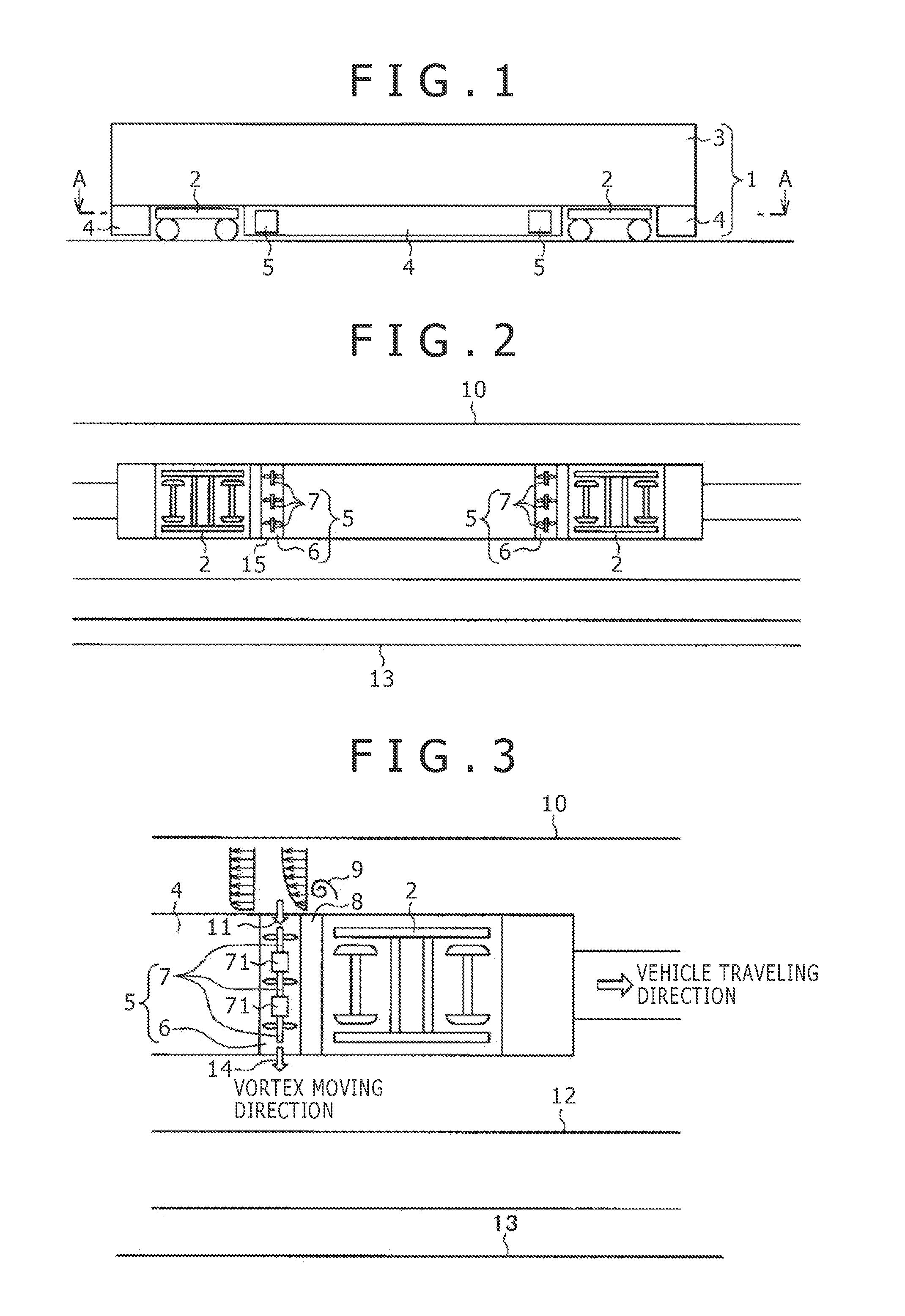
[0036]Firstly, a first embodiment (First Embodiment) of the present invention will be described in detail with reference to FIGS. 1 to 5.

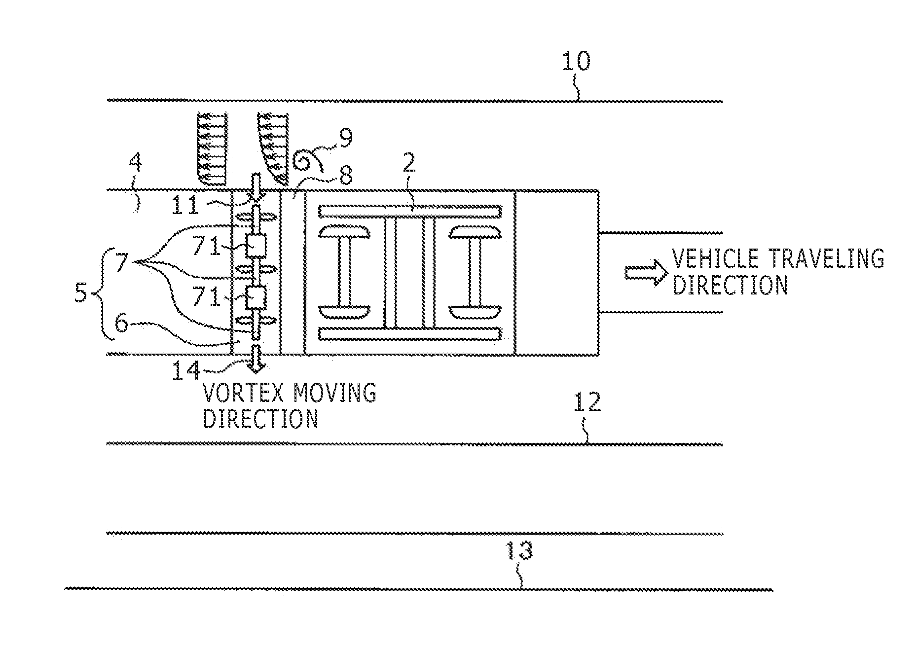
[0037]Referring to attached FIG. 1, a railway vehicle provided with a vehicle vibration suppression device according to the first embodiment of the present invention is composed mainly of a vehicle body 1 and a bogie 2 that carries the vehicle body. Further, the vehicle body 1 is composed mainly of a body structure 3 and a cover 4 that extends at a lower portion of a floor surface of the vehicle body. Furthermore, underfloor equipment is installed on a lower surface of the body structure 3, that is, in a lower portion of the floor surface of the vehicle body, and the cover 4 is mounted in such a manner as to surround (cover) the underfloor equipment. It should be noted that a vehicle vibration suppression control device (hereinafter merely referred to as “flow control device”) according to the present invention, serving as a portion of the underflo...

second embodiment

[0058]Next, a second embodiment (Second Embodiment) of the present invention will be described with reference to attached FIGS. 6 to 8. It should be noted that in the second embodiment, as compared with the above-described first embodiment, the exhaust port of the duct 6 is disposed at a position different from that in the above example so that the vortex is utilized as cooling air for the underfloor device.

[0059]Firstly, as shown in FIGS. 6 and 7, in a railway vehicle according to the second embodiment, a flow control device 25 is composed mainly of a duct 26 bent into an L-shape and a pressure control device 27. It should be noted that the L-shaped duct 26 is disposed under a floor of a body structure 23, in the same manner as the above-described first embodiment.

[0060]Furthermore, referring to these figures, each of the two L-shaped ducts 26 disposed under the floor of the body structure 23 has an intake port. The intake port of the duct on the right side in the figure (in the ve...


PUM


Abstract

There is provided an economical vehicle vibration suppression device capable of efficiently reducing a vortex with a smaller number of devices and controlling the speed of movement in a vehicle longitudinal direction of the vortex.The vehicle vibration suppression device includes a pair of ducts, a pressure control device, and a control unit. The ducts, below a floor surface of a vehicle body, are mounted adjacent to at least a pair of bogies on which the vehicle body is mounted. The ducts are arranged in a direction perpendicular to a traveling direction of the vehicle body and mounted so as to penetrate through both side surfaces of the vehicle body. The pressure control device is mounted within each of the ducts and has openings, one of the openings serving as an intake port and the other opening serving as a discharge port. The pressure control device generates a pressure difference in each of the ducts. The control unit controls start and stop of suction performed by the pressure control device while determining a side surface of the vehicle to be subjected to the suction by the pressure control device on the basis of current distance information of the railway vehicle during currently traveling. The control unit suppresses vibration by driving the pressure control device and sucking a vortex caused by turbulence of air flow generated at a portion of the bogie when the railway vehicle passes through the tunnel.

Description

TECHNICAL FIELD[0001]The present invention relates to a railway vehicle including a flow control device, and more particularly, to a vehicle vibration suppression device suitable for use in the railway vehicle.BACKGROUND ART[0002]For example, in high-speed vehicles such as Shinkansen, there is a need to ensure ride comfort without deteriorating the comfortability of the passengers even during high speed traveling.[0003]For example, as shown in FIG. 9, when a high-speed vehicle, such as Shinkansen, travels in a tunnel section, a vortex is generated at a wall side of the tunnel. A yaw moment and a translational exciting force in a lateral direction, which are caused by pressure fluctuation due to the vortex, are imparted to a vehicle body, leading to an increase in the vibration of the vehicle body. This is already known, for example, in Non-patent Literature 1 below.[0004]Furthermore, as also shown in FIG. 10, in general, when comparing the acceleration responses in the lateral direc...

Claims


Application Information

Patent Timeline
Patent Type & Authority Patents(United States)
IPC IPC(8): B61D17/00B61D17/02B61F5/24
CPCB61D17/02B61F5/24Y02T30/32Y02T30/40Y02T30/00
Inventor HIDAI, MASATAKAGODA, KENJIROMORITA, KIYOSHI
Owner HITACHI LTD
Why Eureka
Try Eureka