Method and apparatus for tilting beams in a mobile communications network

a mobile communications network and beam technology, applied in the direction of electrical equipment, antenna details, antennas, etc., can solve the problems of inflexible solution, inflexible solution, and high prior art solution

Active Publication Date: 2015-05-12
KATHREIN SE
View PDF31 Cites 93 Cited by
  • Summary
  • Abstract
  • Description
  • Claims
  • Application Information

AI Technical Summary

Problems solved by technology

This solution, however, is inflexible.
This is, in effect, wasted spectrum, since the roll-off band is within the allocation of both of the different air interface standards making this prior art solution an expensive (in terms of spectrum license fees) and inflexible solution (as the relative portions of the band dedicated to the GSM standard and the UMTS standard are fixed).
This is generally considered to be undesirable, since the characteristics of these two different air interface standards are very different (e.g. modulation format, data rate, primary application etc.) and most operators would like to be able to set independent tilt angles for each of the different air interface standards, thereby tailoring the coverage and quality of service provided according to the system.

Method used


Image

  • Method and apparatus for tilting beams in a mobile communications network
  • Method and apparatus for tilting beams in a mobile communications network
  • Method and apparatus for tilting beams in a mobile communications network

Examples


Embodiment Construction

[0022]For a better understanding of the present disclosure reference shall now be made to the preferred aspects of the present disclosure, examples of which are illustrated in the accompanying drawings.

[0023]It shall further be understood that the drawings are not to be construed in a limiting way. The scope of protection is defined by the claims as part of this application. For a person skilled in the art it is obvious that several aspects of the following description may as well be combined.

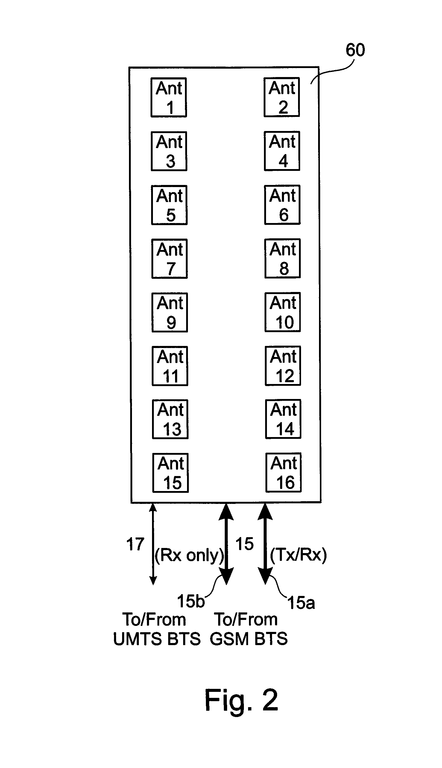
[0024]FIG. 2 shows an outline of an active / passive antenna system allowing an existing first base station 30, using the GSM standard (for example), to be utilized with an antenna-embedded radio system for the UMTS standard (for example). The antenna system 60 of FIG. 2 has three feeds 15a, 15b and 17 to incorporate diversity for both of the different air interface standards. A first feed 15a is a traditional coaxial feed 10 which transports high-power transmit and low-power receive signals to a...


PUM


Abstract

An antenna array for a mobile communications network is disclosed which comprise mechanical devices for altering a direction of a first beam and electronic beam forming apparatus for shaping a second beam. A method for tilting radio beams in a mobile communications network using the antenna array is also disclosed. The method comprises mechanical tilting a first protocol radio beam and electronic tilting a second protocol radio beam.

Description

CROSS REFERENCE TO OTHER APPLICATIONS[0001]The present application is related to U.S. patent application Ser. No. 12 / 648,773 entitled “Active Antenna Array and Method for relaying first and second Protocol Radio Signals in a Mobile Communications Network” filed Dec. 29, 2009, which is incorporated in its entirety. The present application is further related to U.S. patent application Ser. No. 12 / 648,852 entitled “Active Antenna Array for a Mobile Communications Network with Multiple Amplifiers Using Separate Polarisations for Transmission and a Combination of Polarisations for Reception of Separate Protocol Signals” filed Dec. 29, 2009, which is incorporated in its entirety. The present application is further related to U.S. patent application Ser. No. 12 / 648,713 entitled “Active Antenna Array with Multiple Amplifiers for a Mobile Communications Network and Method of Providing DC Voltage to at least one Processing Element” filed Dec. 29, 2009, which is incorporated in its entirety. T...

Claims


Application Information

Patent Timeline
Patent Type & Authority Patents(United States)
IPC IPC(8): H01Q3/00H01Q1/24H01Q25/00
CPCH01Q1/246H01Q25/00
Inventor KENINGTON, PETERWECKERLE, MARTINNEUMANN, DIRKLINEHAN, KEVIN E
Owner KATHREIN SE
Why Eureka
Try Eureka