Nuclear fuel cladding with high heat conductivity and method for making same

a technology of nuclear fuel and heat conductivity, which is applied in the field of nuclear fuel, can solve the problems of cladding swelling, loss of fuel confinement, and general brittleness to withstand the operating conditions of nuclear fuel cladding, and achieve the effect of optimizing the transfer of thermal energy generated

Active Publication Date: 2015-05-12
COMMISSARIAT A LENERGIE ATOMIQUE ET AUX ENERGIES ALTERNATIVES
View PDF13 Cites 8 Cited by
  • Summary
  • Abstract
  • Description
  • Claims
  • Application Information

AI Technical Summary

Benefits of technology

[0010]It is accordingly one of the objects of this invention to provide a nuclear fuel cladding totally or partially made of a composite material which, when irradiated and at temperatures of between 800° C. and 1200° C., is capable of mechanically maintaining the fuel within the cladding while enabling optimal transfer of the thermal energy generated towards the coolant gas.
[0012]As shown below, when irradiated and at temperatures between 800° C. and 1200° C. (preferably, between 800° C. and 1000° C., or even equal to 800° C.), the nuclear fuel cladding according to the invention has a thermal conductivity which allows the transfer of heat towards the coolant to be improved, whilst at the same time preserving the thermomechanical (high melting point) and mechanical (reduced brittleness) properties, which are inherent to CMCs and which enable optimum confinement of the fuel contained within the cladding.
[0013]According to a preferred embodiment, the matrix of the ceramic matrix composite material further comprises silicon carbide SiC. Thus, for example, silicon carbide SiC, represents less than 50% (typically, from 1% to 50%) by volume of the matrix, preferably less than 25% (typically from 1% to 25%), and still more preferably, less than 10% (typically, from 1% to 10%). The addition of these varying quantities of SiC enables the matrix properties (such as the thermal conductivity) to be optimally adapted to the prevailing conditions. The incorporation of SiC within the matrix also allows its thermomechanical compatibility with SiC fibers to be improved: for example, the matching between the thermal expansion coefficients allows the effects of a differential expansion between the matrix and the fibers, which could lead to cracking of the nuclear fuel cladding, to be reduced.
[0014]In a preferred embodiment, the silicon carbide SiC in the matrix represents between 5% and 15% by volume of the matrix (in particular when the matrix contains TiC). Unexpectedly, as illustrated below, such a matrix composition makes it possible to achieve optimal thermal conductivity.
[0019]Concerning their composition, the fibers are made of SiC, such that they are particularly well suited to the context of the invention because SiC has an excellent neutron and thermal stability.

Problems solved by technology

Ceramics, although they meet these criteria, are generally too brittle to withstand the operating conditions of a nuclear fuel cladding.
Indeed, fission reactions within the nuclear fuel generate solid and gaseous fission products which cause cladding swelling.
When subjected to such loads, the ceramics that form the cladding may break-up and cause a loss of fuel confinement.
However, for a given temperature, the thermal conductivity of CMCs of the SiCf / SiC type may strongly decrease after it has been subjected to irradiation.
During the operation of a “He-GFR” nuclear reactor subjected to high temperatures, such CMCs therefore prove to be inappropriate for the removal of thermal energy from the nuclear fuel cladding towards the coolant gas.

Method used


Image

  • Nuclear fuel cladding with high heat conductivity and method for making same
  • Nuclear fuel cladding with high heat conductivity and method for making same
  • Nuclear fuel cladding with high heat conductivity and method for making same

Examples


first embodiment

[0083]In a first embodiment, the number of pulses in each of the TiC and SiC deposition sequences is reduced such that the deposited layer is discontinuous.

[0084]The TiC deposition conditions are those mentioned in the previous example.

[0085]For SiC deposition, the conditions are also similar to those of TiC deposition, except for the following parameters:[0086]gas precursors: H2 and MTS (methyltrichlorosilane of formula CH3SiCl3)[0087]temperature from 900° C. to 1050° C.[0088]working pressure from 1.5 kPa to 5 kPa[0089]αSiC (PH2 / PMTS) from ¼ to 5 (from ¼ to ½, residual carbon is seen to be formed, and beyond 3, there is no more residual carbon. However, the deposition rate increases when αSiC increases).

[0090]It should be noted that the deposition rate of the SiC layer is proportional to the temperature and pressure values shown.

[0091]In the present case, the following parameters effectively used for depositing SiC are as follows:[0092]temperature=1050° C.[0093]working pressure=4 k...

second embodiment

[0099]In a second embodiment, nano-sequenced depositions are made, namely depositions for which layers of different characteristics, having a mean thickness of 10 to 100 nm, are deposited consecutively. For that purpose, the precursor pulses specifically intended for TiC and SiC are produced consecutively (for instance, 40 pulses for SiC and 80 pulses for TiC, or 20 pulses for SiC and 40 pulses for TiC).

third embodiment

[0100]In a third embodiment, the SiC and TiC precursors are introduced together. Generally, the precursors and operating conditions are then selected from the following:[0101]TiCl4, SiCl4, CCl4H2 / 950° C. to 1150° C. / 100 kPa[0102]TiCl4, SiCl4, C3H8, H2 / 950° C. to 1150° C. / 4−40 kPa[0103]TiCl4, SiCl4, CH4, H2 / 950° C. to 1150° C. / 7 kPa[0104]TiCl4, SiH2Cl4, C4H10, H2 / 950° C. to 1150° C. / 100 kPa[0105]TiCl4, CH3SiCl3, H2 / 950° C. to 1150° C. / 1 kPa to 100 kPa[0106]TiCl4, SiCl4, C3H8, H2 / 950° C. to 1150° C. / 100 kPa

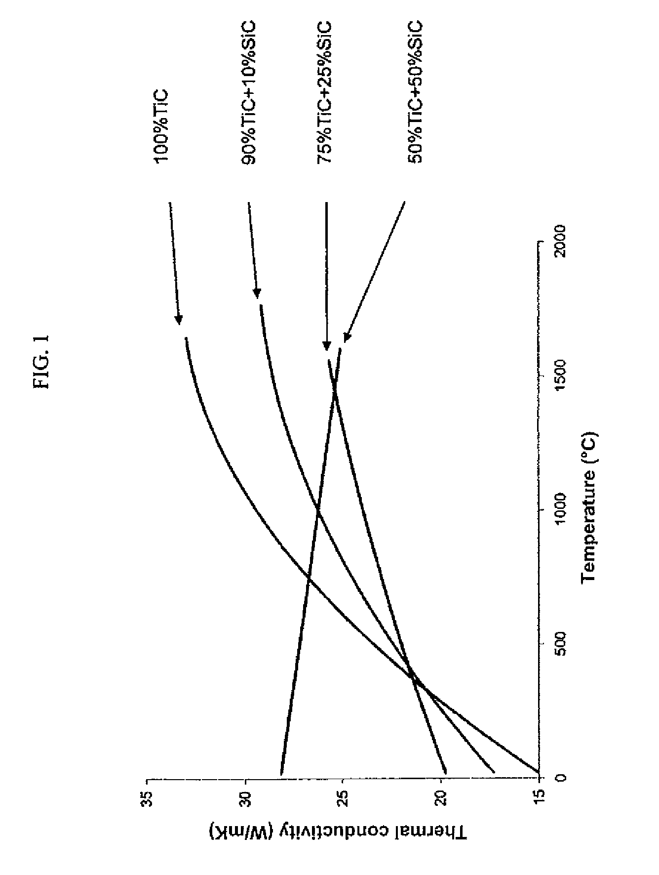
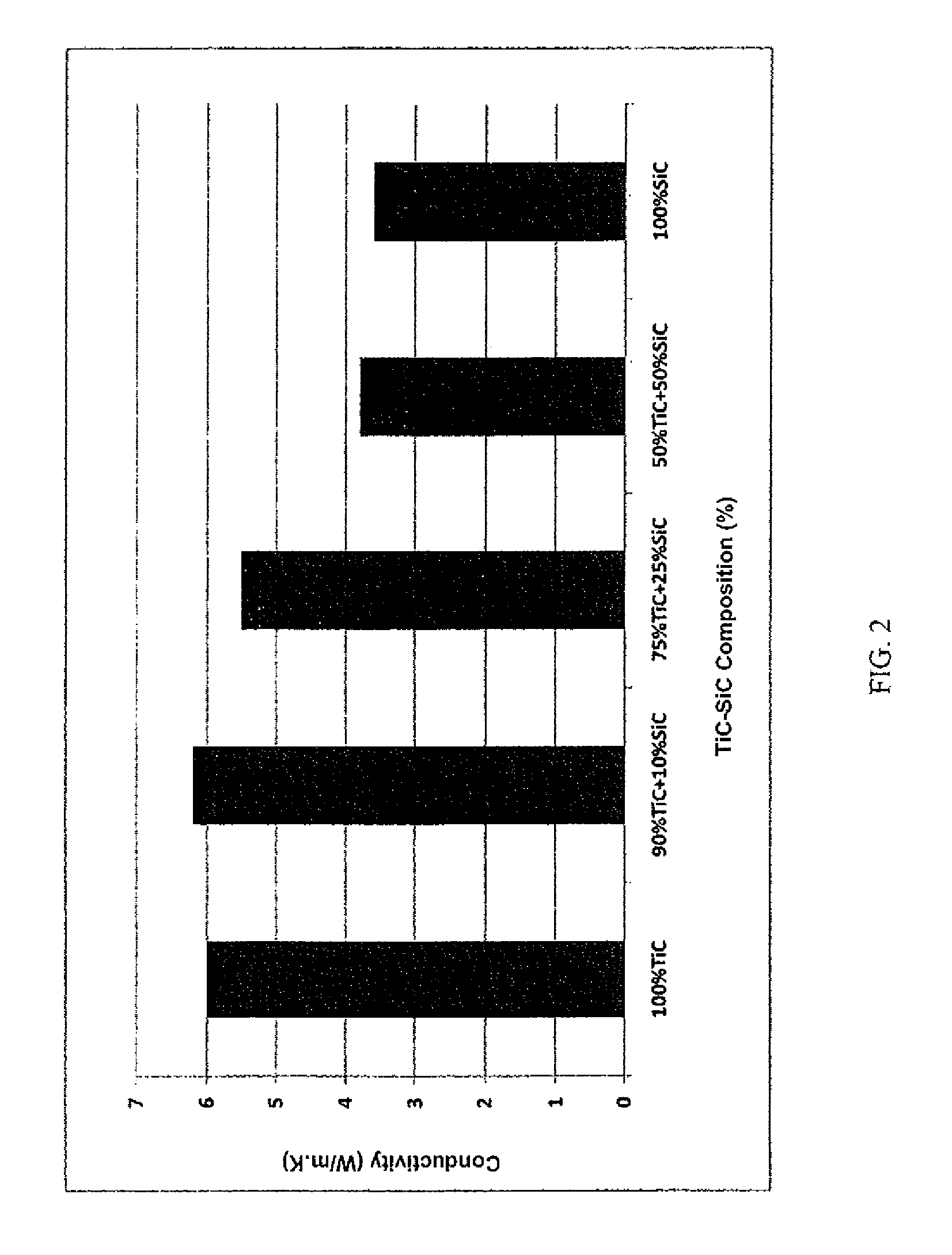
[0107]2—Thermal Properties of Ceramic Matrix Composite (CMC) Materials Comprising TiC.

[0108]Ceramic materials (without fibers and an interphase layer), with the same composition as the matrix of the four TiC-based CMCs made previously, are manufactured by sintering under pressure.

[0109]The four ceramic materials have the following TiC / SiC compositions in volume percentage: 100 / 0, 90 / 10, 75 / 25, 50 / 50.

[0110]These ceramic materials allow the relative thermal conductivity of the four pr...


PUM

PropertyMeasurementUnit
thicknessaaaaaaaaaa
thicknessaaaaaaaaaa
temperaturesaaaaaaaaaa

Abstract

The invention relates to a nuclear fuel cladding totally or partially made of a composite material with a ceramic matrix containing silicon carbide (SiC) fibers as a matrix reinforcement and an interphase layer provided between the matrix and the fibers, the matrix including silicon carbide as well as at least one of the following additional carbides: titanium carbide (TiC), zirconium carbide (Zrc), and ternary titanium silicon carbide (Ti3SiC2). When irradiated and at temperatures of between 800° C. and 1200° C., said cladding can mechanically maintain the nuclear fuel within the cladding while enabling optimal thermal-energy transfer towards the coolant. The invention also relates to a method for making the nuclear fuel cladding.

Description

FIELD OF THE INVENTION[0001]This invention generally pertains to the field of nuclear fuel and, in particular, it relates to a nuclear fuel cladding for helium-cooled “high temperature” nuclear reactors as well as a process for manufacturing the same.BACKGROUND OF THE INVENTION[0002]Among the nuclear reactors of the future, the Fast Neutron Reactor (FNR), which uses helium as the coolant gas (the so-called “He-GFR” reactor), may be mentioned. This reactor is a so-called “high-temperature” reactor because during operation the temperature of its core generally lies in the range between 800° C. and 1200° C.[0003]As described in patent application EP 1 913 600, a nuclear fuel cladding employed in such a reactor may be provided as a plate, a cylinder, a sphere or a network of cavities.[0004]When subjected to the above-mentioned temperature conditions, this cladding requires the use of high-melting point refractory materials (in order to ensure sufficient thermomechanical stability to mai...

Claims


Application Information

Patent Timeline
Patent Type & Authority Patents(United States)
IPC IPC(8): G21C3/02G21C3/06C04B35/56C04B35/628C04B35/632C04B35/80G21C3/07G21C3/20G21C21/02
CPCC04B35/5611C04B35/5615C04B35/5622C04B35/62873C04B35/62884C04B35/62894C04B35/62897C04B35/6325C04B35/806G21C3/07G21C3/20G21C21/02C04B35/6286C04B2235/3232C04B2235/3244C04B2235/3418C04B2235/3813C04B2235/3826C04B2235/444C04B2235/5244C04B2235/5252C04B2235/614C04B2235/77Y02E30/40Y02E30/30C04B35/80
Inventor CABRERO, JULIENPAILLER, RENEAUDUBERT, FABIENNE
Owner COMMISSARIAT A LENERGIE ATOMIQUE ET AUX ENERGIES ALTERNATIVES
Why Eureka
Try Eureka