Internal imaging system

a technology of imaging system and internal flaw, applied in the direction of material analysis using wave/particle radiation, instruments, specific gravity measurement, etc., can solve the problems of destructive or direct contact methods, detection of many internal flaws in railway track components, and inability to achieve destructive inspection methods

Active Publication Date: 2015-05-12
LORAM TECH INC
View PDF17 Cites 36 Cited by
  • Summary
  • Abstract
  • Description
  • Claims
  • Application Information

AI Technical Summary

Problems solved by technology

Currently the detection of many internal flaws of railway track components may be found through either destructive or direct-contact methods.
Destructive inspection methods may not be desired as the component, or at least a portion of the component, is damaged and / or destroyed.
Direct-contact methods of inspection are typically slow, reducing the amount of track that may be inspected during a single date to detect potential flaws in the railway track components.
Some flaws may currently be detected using a destructive inspection method.
For example, a hollow region in a tie can be exposed through a destructive method such as cutting a cross-section with a chain saw.
This method of determining faulty ties may not be highly accurate in determining whether a tie is faulty.
For example, one flaw is a crack in a concrete tie.
Often a crack in a concrete tie may be positioned under the ballast level and thus, a track inspector could easily fail to detect this flaw.
Taking the time to remove the ballast, inspect each tie at the sub-ballast level, and then replace the ballast takes far too much maintenance time on a rail line.
This may be due to the combination of standing water and electricity flowing through the rail acting to rust and erode the rail-base at an increased rate.

Method used


Image

  • Internal imaging system
  • Internal imaging system
  • Internal imaging system

Examples


Embodiment Construction

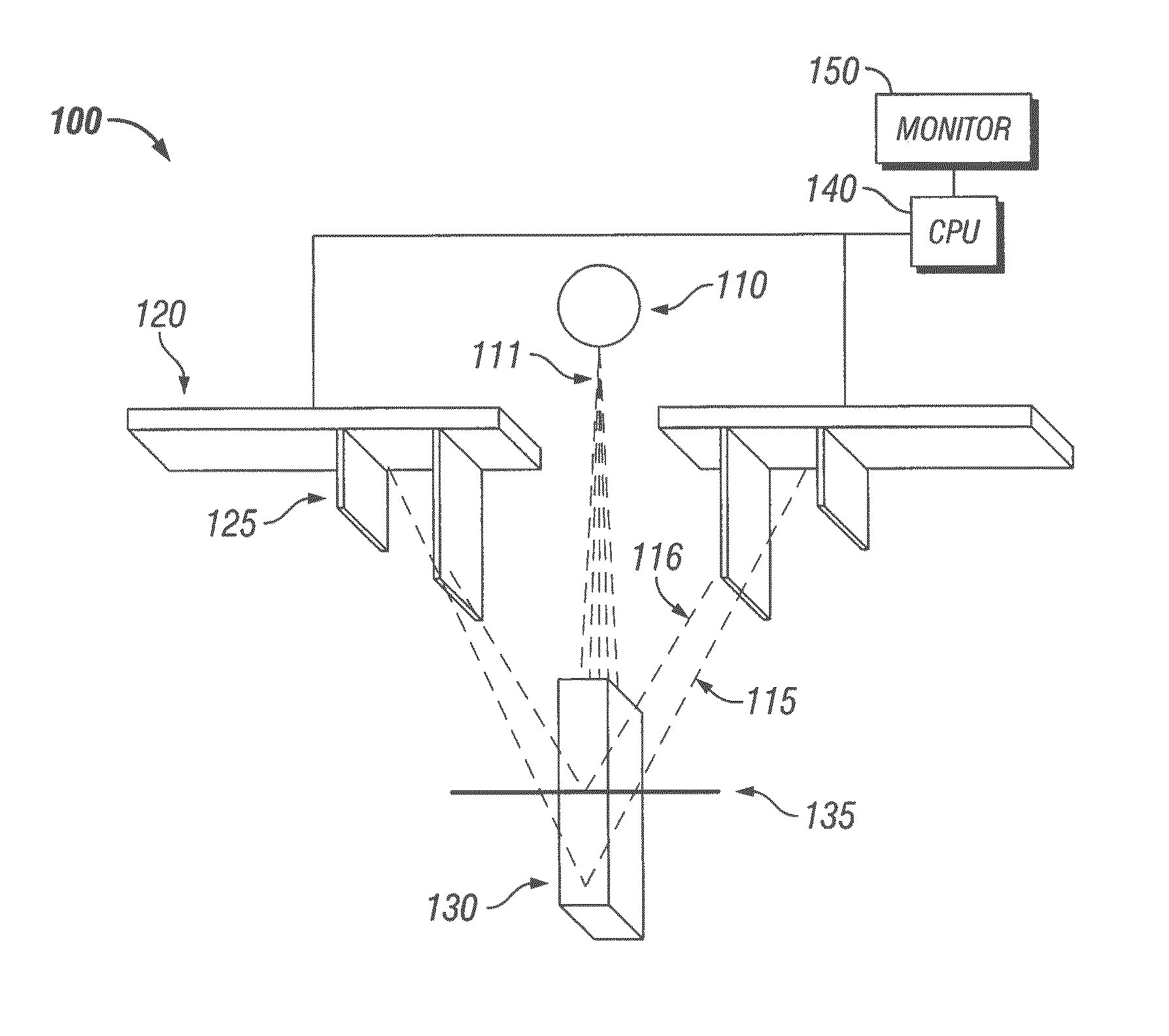
[0043]The present disclosure is directed to an internal inspection system that uses backscatter x-ray technology. The internal inspection system may be used alone or synchronized with a video scan or 3D camera scan to provide a surface scan super-imposed on the internal image. One such surface scan is the Aurora system from Georgetown Rail Equipment Company of Georgetown, Tex., as disclosed in U.S. Pat. No. 7,616,329 entitled System and Method for Inspecting Railroad Track, which is herein incorporated by reference in its entirety. The x-ray inspection and video or 3D camera scan may be synchronized by the use of a wheel encoder and / or GPS system. The video scan may provide color images or grayscale images. Alternatively, a comparison of a backscatter x-ray scan and a surface scan may be used to analyze railway components instead of super-imposing the surface scan onto the backscatter x-ray scan. For example, a side-by-side comparison of two scans may be used.

[0044]The present discl...


PUM

PropertyMeasurementUnit
distanceaaaaaaaaaa
power consumptionaaaaaaaaaa
densityaaaaaaaaaa

Abstract

A system for the inspection of the internal structure of a target includes at least one x-ray source that emits collimated x-rays to irradiate the target. At least one detector is positioned to detect backscatter x-rays from the target. The detector may include a collimation slot that limits the field of view of the detector. The target may be a railway component and the system may inspect the internal structure of the component as it is moved along the railway by a vehicle. The system may detect a change in the density of a target based on a comparison of the detected backscatter x-rays. The use of a plurality of segmented backscatter x-ray detectors having a collimation slot may pixelate the internal image in the direction of the collimation slot.

Description

RELATED APPLICATIONS[0001]The present application claims the benefit of U.S. Provisional Patent Application Ser. No. 61 / 596,552, filed on Feb. 8, 2012 and entitled INTERNAL IMAGING OF RAILWAY COMPONENTS, the disclosure of which is incorporated herein by reference in its entirety.BACKGROUND[0002]1. Field of the Disclosure[0003]The embodiments described herein relate to an internal imaging system using the detection of backscatter x-rays and may be used for the internal inspection of railway track components.[0004]2. Description of the Related Art[0005]Currently the detection of many internal flaws of railway track components may be found through either destructive or direct-contact methods. Destructive inspection methods may not be desired as the component, or at least a portion of the component, is damaged and / or destroyed. Direct-contact methods of inspection are typically slow, reducing the amount of track that may be inspected during a single date to detect potential flaws in the...

Claims


Application Information

Patent Timeline
Patent Type & Authority Patents(United States)
IPC IPC(8): G01N23/02G01N9/24G01N9/36G01N23/203
CPCG01N23/203G01N9/36G01N9/24B61K9/10
Inventor BELCHER, JEBAARON, CHARLES WAYNE
Owner LORAM TECH INC
Why Eureka
Try Eureka