Compact can transfer system

Active Publication Date: 2015-05-19
MALL & HERLAN
View PDF16 Cites 5 Cited by
  • Summary
  • Abstract
  • Description
  • Claims
  • Application Information

AI Technical Summary

Benefits of technology

[0008]Thus it is an object of the present invention to provide

Problems solved by technology

Thus, the compactness of the

Method used


Image

  • Compact can transfer system
  • Compact can transfer system
  • Compact can transfer system

Examples


Embodiment Construction

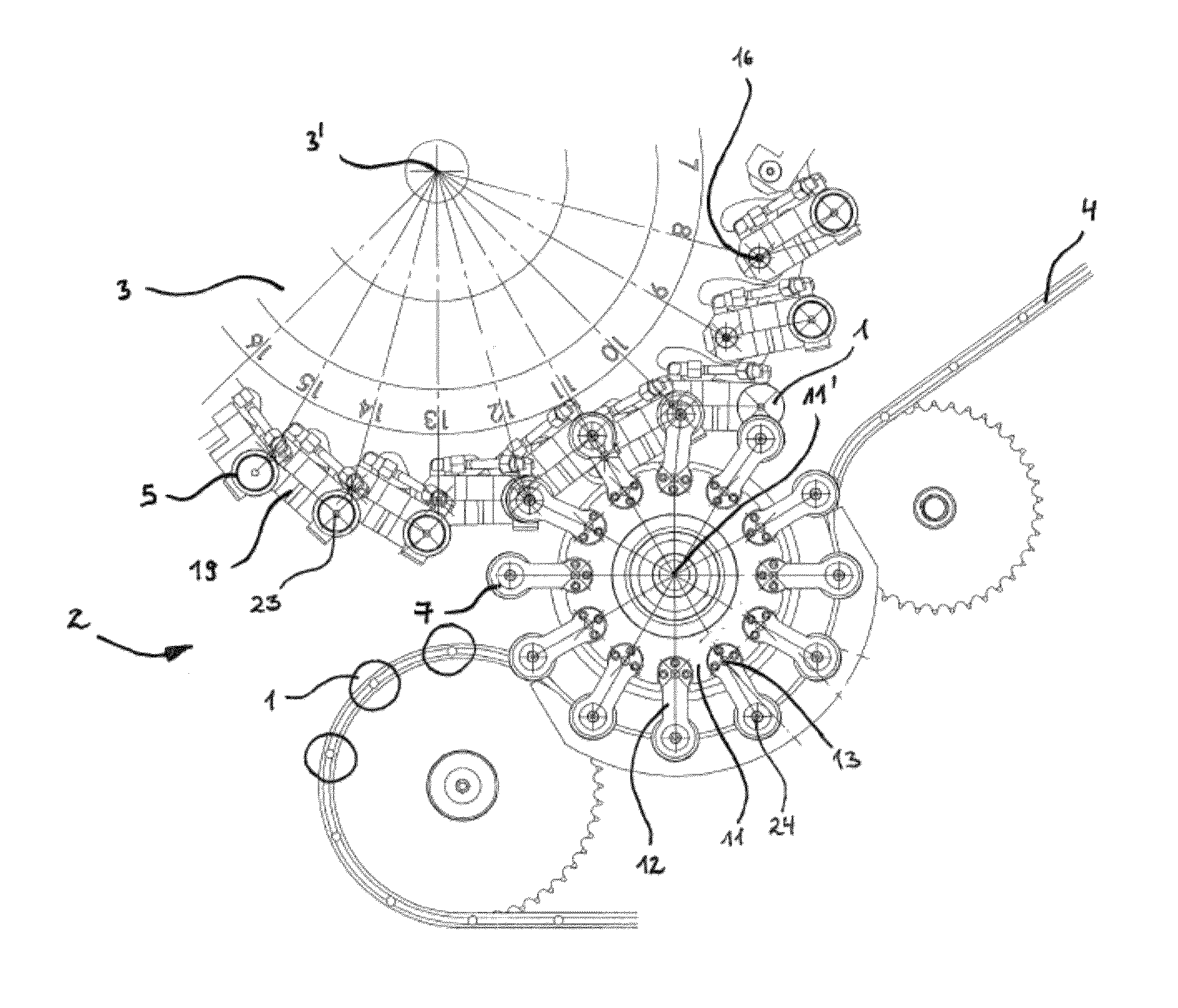
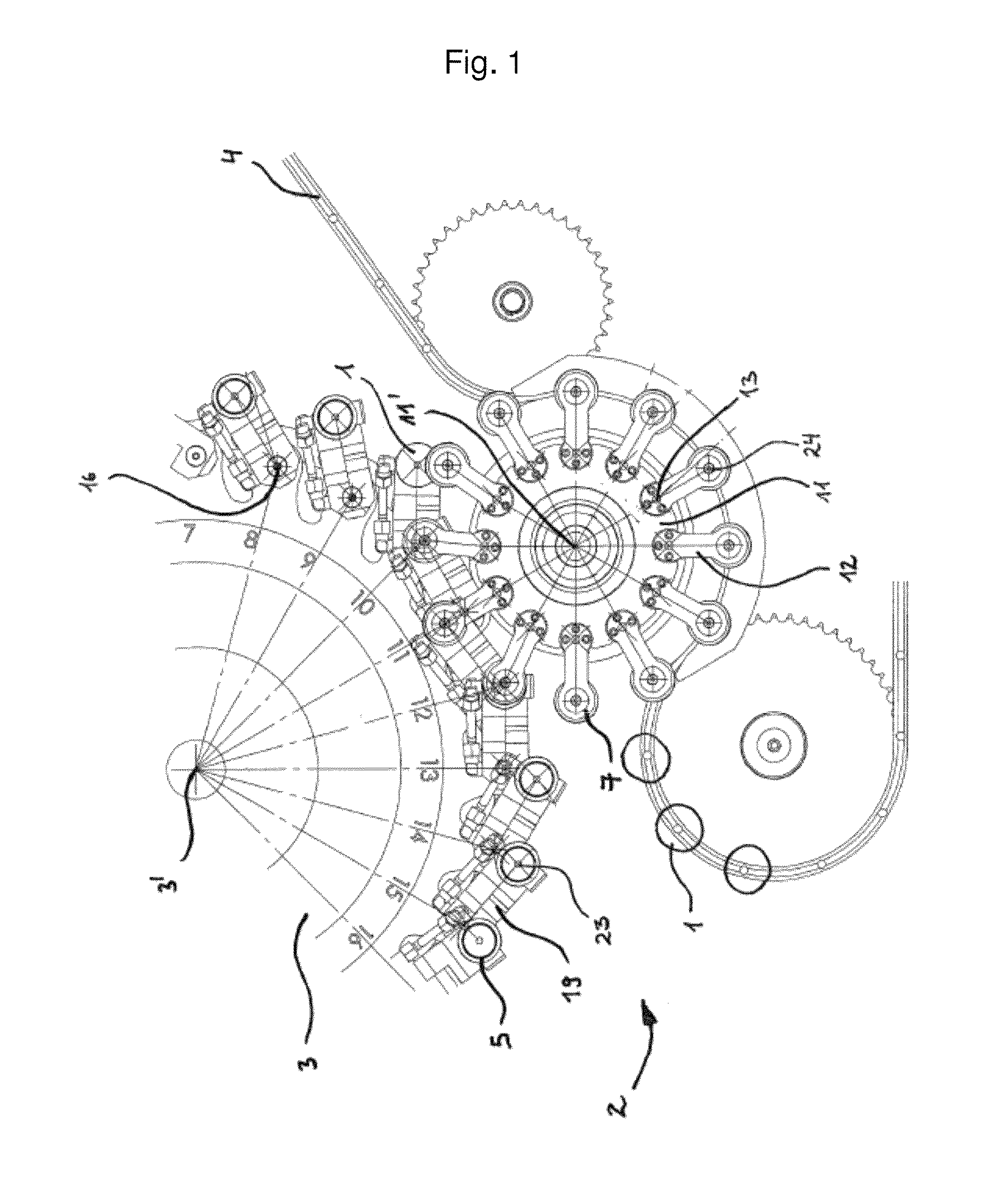
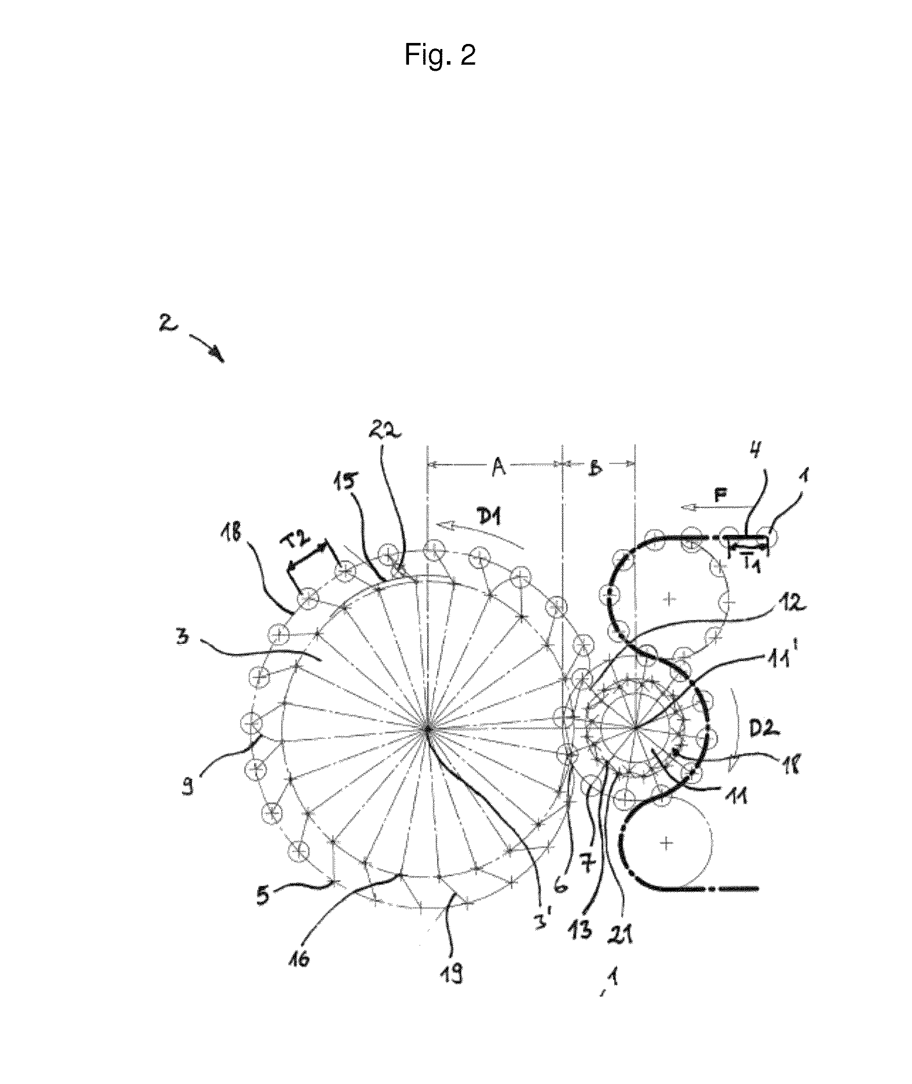
[0044]A transfer device 2 in FIG. 1 includes a mandrel wheel 3 and a transfer wheel 11 and is used for transferring an object 1 from the mandrel wheel 3 through the transfer wheel 11 to a transport device 4. The mandrel wheel 3 is driven to rotate about a rotation axis 3′, the transfer wheel 11 is driven to rotate about a rotation axis 11′, wherein the rotation axes 3′ and 11′ are arranged parallel to one another. In the portion of the periphery of the mandrel wheel 3, supports are arranged that are configured as receiving mandrels 5 and in the portion of the periphery of the transfer wheel 11, supports 7 are arranged that are configured as transfer supports. The number of the transfer supports 7 at the transfer wheel, in this embodiment 12, is smaller than the number of the receiving mandrels 5 at the mandrel wheel 3, in this embodiment 24, wherein nine receiving mandrels 5 are visible at the cutout of the mandrel wheel 3 illustrated in the figure. The transfer supports 7 are respe...


PUM


Abstract

A transfer device comprising a mandrel wheel; and a transfer wheel, respectively driven to rotate about rotation axes that are parallel to one another and which respectively include supports in their peripheries for objects to be imprinted or processed otherwise, wherein a distance of the supports at the mandrel wheel from a rotation axis of the mandrel wheel is variable between a minimum distance and a maximum distance, and the mandrel wheel and the transfer wheel are arranged adjacent to one another so that objects are transferrable from a transport device through the transfer wheel to a respective support at the mandrel wheel or vice versa from the mandrel wheel through the transfer wheel to a transport device, wherein the supports are respectively attached to the transfer wheel through a transfer pivot arm so that they are pivotable about a pivot axis.

Description

CROSS REFERENCE TO RELATED APPLICATIONS[0001]This application claims priority under 35 USC §119 to German Patent Application No. 10 2011 081 590.2 filed on Aug. 25, 2011, which application is hereby incorporated by reference.TECHNICAL FIELD[0002]The invention relates to a transfer device with a mandrel wheel and a transfer wheel respectively driven so that they rotate about rotation axes that are parallel to one another in order to transfer objects from a transport device through the transfer wheel to supports at the mandrel wheel or vice versa, from the mandrel wheel through the transfer wheel to a transport device.[0003]The objects to be transferred are for example cans or other cylindrical hollow elements with bases.BACKGROUND OF THE INVENTION[0004]Transfer devices are known whose mandrel wheel and transfer wheel are arranged adjacent to one another and which include receiving mandrels or supports in their periphery for objects to be imprinted or processed in another manner, wher...

Claims


Application Information

Patent Timeline
IPC IPC(8): B65G47/84
CPCB65G47/848B65G47/84B65G2201/0235
Inventor GOEB, CLAUDE
Owner MALL & HERLAN
Why Eureka
Try Eureka