
Electronic adapter for controlling a bistable valve

a technology of electronic adapters and bistable valves, applied in the direction of valve details, polarised relays, electromagnets, etc., can solve the problems of monostable valves that require a remarkable amount of energy, the temperature of the valve, the environment, etc., and achieve the effect of reducing the temperature of the medium to be controlled, reducing the temperature of the medium, and reducing the energy consumption

Inactive Publication Date: 2011-04-21
DIENER PRECISION PUMPS
View PDF16 Cites 2 Cited by
  • Summary
  • Abstract
  • Description
  • Claims
  • Application Information

AI Technical Summary

Benefits of technology

[0012]The first signal event can be a signal edge with a first slope, wherein the second signal event is a signal edge with a second, opposite slope, which is the typical way to control a monostable valve. Such an adapter may be used to apply a bistable valve in an environment where monostable behaviour is required. Existing monostable valves may be replaced by bistable valves equipped with the electronic adapter. This allows to combine the benefits of monostable valves with those of bistable ones while avoiding their respective drawbacks. In particular, the advantages can include, for example, simple control, compatible with monostable valves, defined switching state in case of power failure, less energy consumption than a monostable valve, no heating of the valve and the medium to be controlled, no heating of the environment, and / or less space requirement than a monostable valve since no over-sizing of the solenoid is required.
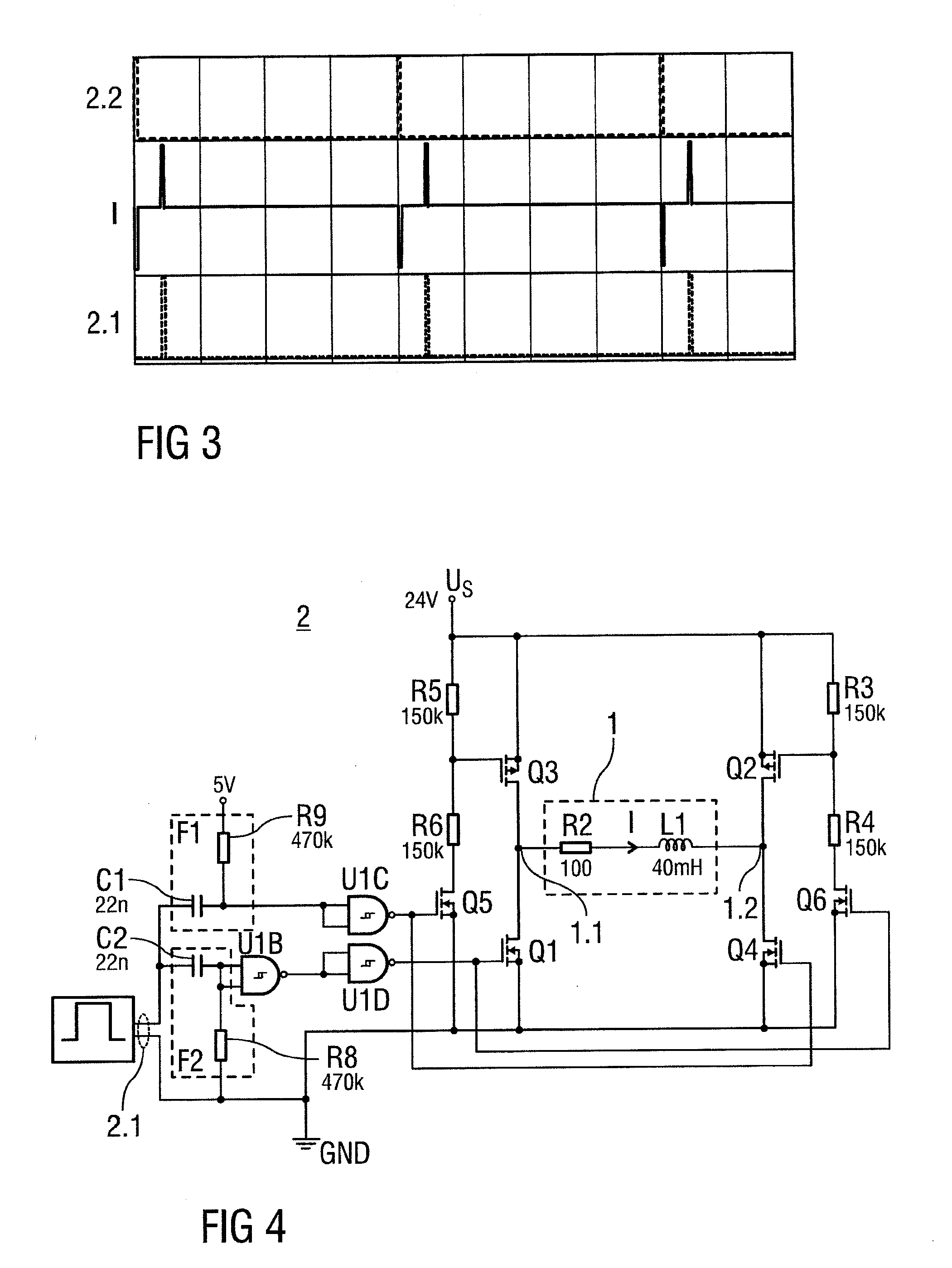
[0015]Energy storages, in particular capacitors tend to self-discharge over time when not being recharged. When controlling monostable valves the input voltage is usually reduced to a holding level after switching to the instable state, wherein the holding level is remarkably lower than the switching voltage. However the energy store of the adapter needs to be charged to a level at least as high as the switching voltage in order to reliably switching the valve to a default switching state. Charging or maintaining simply with the input voltage at holding level is insufficient. Instead, a boost converter is used for converting the input voltage at holding level into a voltage high enough to charge the energy store or maintain its charge. Boost converters usually chop a DC voltage and apply the resulting pulsed voltage to an inductor where voltage peaks at much higher level are induced. These voltage peaks may then be used for charging an energy store such as a capacitor. The energy store voltage may therefore be remarkably higher than the initial DC voltage. This allows for reliably switching the valve into its default switching state even after a long-term input voltage at holding level.
[0017]The alternating voltage may have a cycle period smaller than twice the switch time period. This avoids unintentional switching of the valve by the pulsed voltage since its pulses are too short to switch the switching states.
[0018]Unintentional switching may also be avoided by keeping the amplitude of the alternating voltage smaller than the switch voltage.
[0019]The valve may comprise an armature consisting of a magnetisable material, moveably arranged inside a valve body housing consisting of a non-magnetic material. An inductivity of the coil may be influenced by a position of the armature since an air gap between the armature and the yoke is different between the two stable positions corresponding to the switching states. A sensor winding may be arranged on the yoke for detecting the switching state from a sensor voltage induced in the sensor winding by a magnetic flux of the solenoid caused by the alternating voltage. Thus the current switching state or position can be detected without much effort.
[0021]The electronic adapter may be arranged as an integrated circuit, e.g. a customized integrated circuit in order to reduce space requirement and costs.

Problems solved by technology

However, the monostable valve requires a remarkable amount of energy when being kept in its instable state.
Besides the energy consumption this usually results in warming of the valve, its environment and above all warming of the medium to be controlled which may be particularly undesirable in some applications.
Hence, they neither have remarkable power consumption nor do they heat the medium to be controlled.
However, they do not have a default switching state in case of a power loss which keeps them from being applied in environments where this is critical.
Furthermore, controlling the bistable valve is more complicated since pulses have to be generated and the polarity of the switch voltage has to be changed.
Failure of the control signals, e.g. permanent current feeding of the bistable valve, which is dimensioned for pulse operation only, may result in overheating and destruction of the valve.

Method used


Image

  • Electronic adapter for controlling a bistable valve
  • Electronic adapter for controlling a bistable valve
  • Electronic adapter for controlling a bistable valve

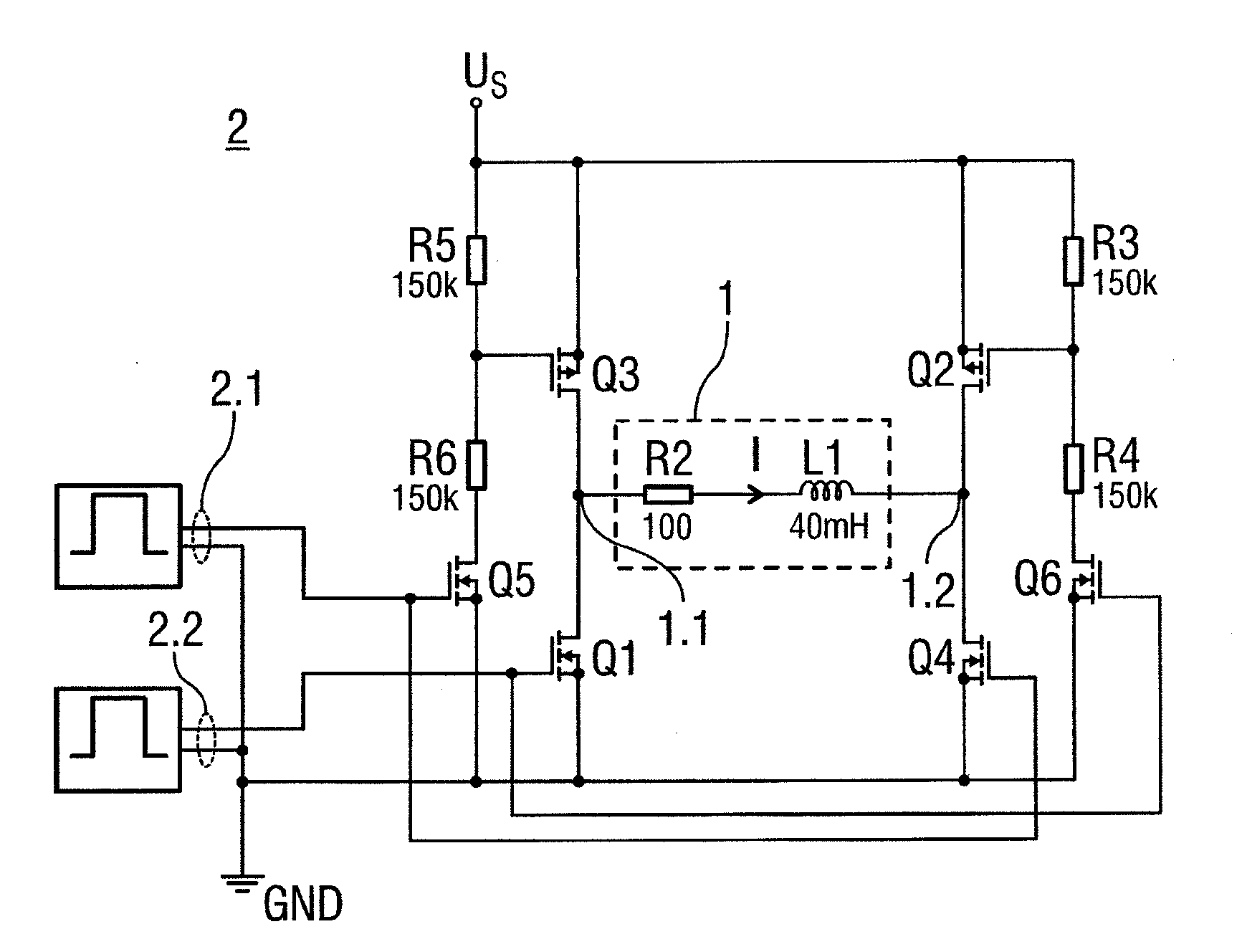
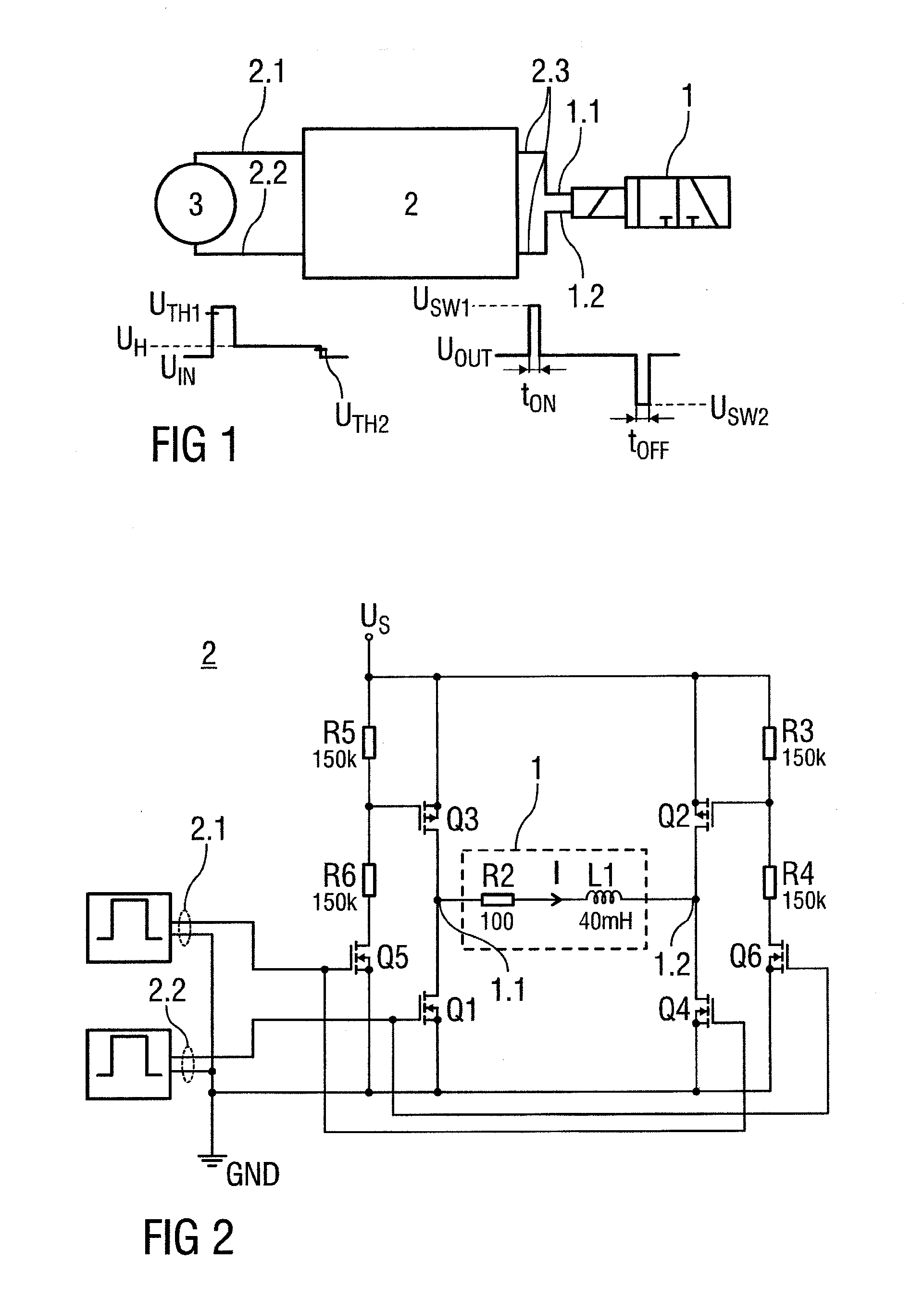
Examples


Embodiment Construction

[0035]Corresponding parts are marked with the same reference symbols in all figures.

[0036]FIG. 1 is a schematic view of a bistable valve 1 for controlling liquid or gasiform media with an electronic adapter 2 for converting control signals. The bistable valve 1 has a first and a second stable switching state. The valve is operated by applying respective switch voltages USW1, USW2 with opposite polarities for at least a switch time period tON, tOFF at electric terminals 1.1, 1.2 of the valve 1. If the valve 1 is in the first switching state, applying the switch voltage USW1 with a first polarity for at least the switch time period tON, tOFF to the electric terminals 1.1, 1.2 causes the valve to change to the second switching state. If the valve 1 is in the second switching state, applying the switch voltage USW2 with an opposite second polarity for at least the switch time period tON, tOFF causes the valve 1 to change from the second to the first switching state. The electronic adapt...


PUM


Abstract

An electronic adapter and a method for controlling a bistable valve for liquid or gaseous media is provided. The valve has a first and a second stable switching state, wherein in the first switching state applying a switch voltage with a first polarity for at least a switch time period to electric terminals of the valve causes the valve to change to the second switching state and wherein in the second switching state applying a switch voltage with an opposite second polarity for at least the switch time period causes the valve to change from the second to the first switching state, wherein the adapter has at least one input connectable to a control unit and an output connectable to the terminals, wherein the adapter is arranged for outputting the switch voltage with the first polarity for at least the switch time period upon detection of a first signal event at the input and wherein the adapter is arranged for outputting the switch voltage with the second polarity for at least the switch time period upon detection of a second signal event at the input.

Description

[0001]This nonprovisional application claims priority under 35 U.S.C. §119(a) to European Patent Application No. 09 173 312.1, which was filed in Germany on Oct. 16, 2009, and which is herein incorporated by reference.BACKGROUND OF THE INVENTION[0002]1. Field of the Invention[0003]The invention relates to an electronic adapter and a method for controlling a bistable valve.[0004]2. Description of the Background Art[0005]Valves may be applied in medical technology, e.g. in dialysis machines and analyzers, and in ink jet printers or in a plurality of fields where aggressive or delicate media have to be controlled.[0006]In most applications monostable valves are preferred over bistable ones. Monostable valves have only one stable switching state, i.e. they may be switched to an instable state, e.g. by applying a voltage to a solenoid and remain in the instable state as long as the voltage is maintained. As soon as the voltage falls below a certain level the valve drops back in its stabl...

Claims


Application Information

Patent Timeline
Patent Type & Authority Applications(United States)
IPC IPC(8): F16K31/02
CPCH01F7/18F16K31/0675
Inventor WALTER, RAIMOND
Owner DIENER PRECISION PUMPS
Learn More