Lighting device

a technology of light strip and light plate, which is applied in the direction of fixed installation, lighting and heating equipment, instruments, etc., can solve the problem of wide light strip however

Active Publication Date: 2015-05-19
AUDI AG
View PDF16 Cites 7 Cited by
  • Summary
  • Abstract
  • Description
  • Claims
  • Application Information

AI Technical Summary

Benefits of technology

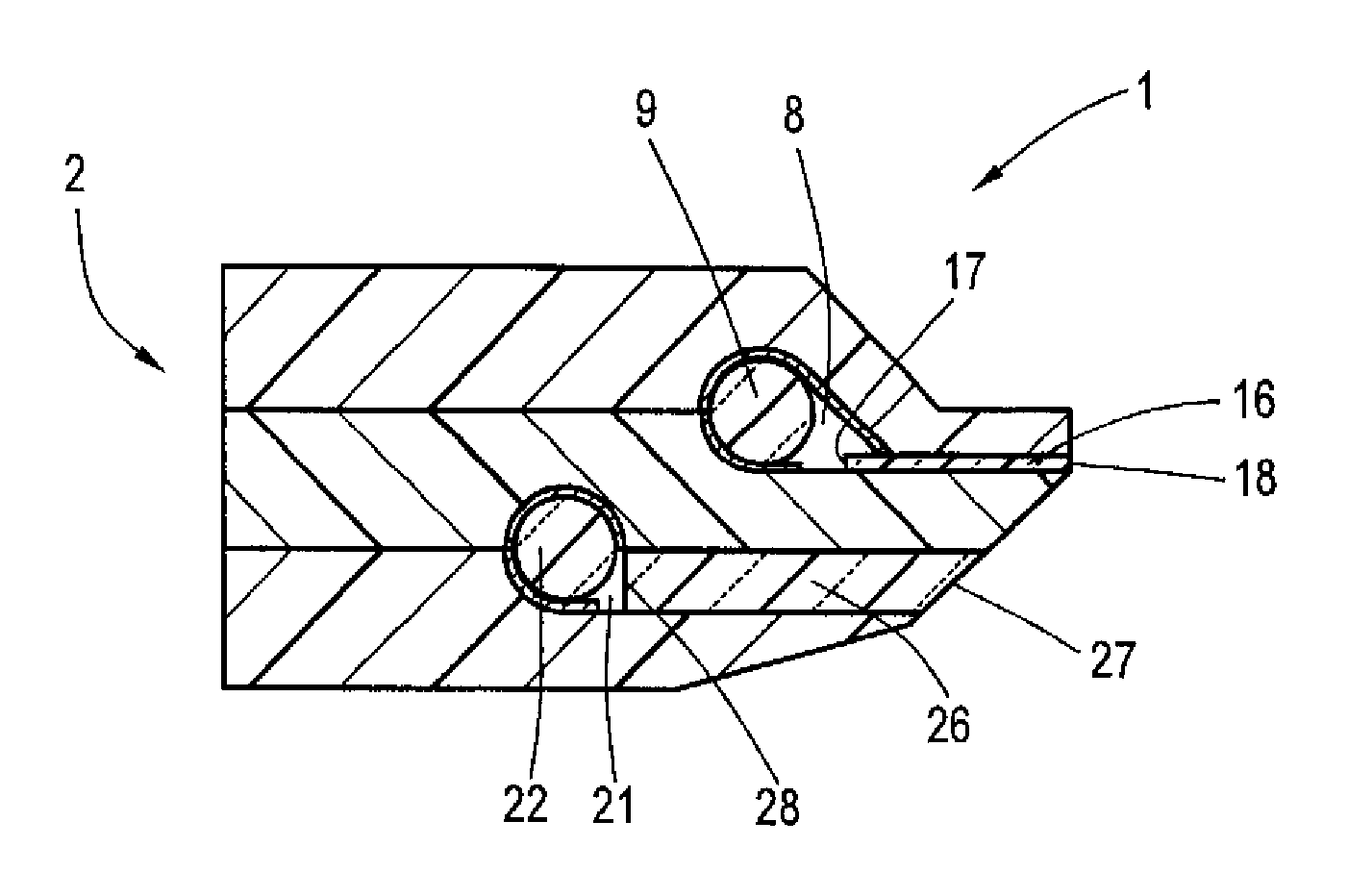
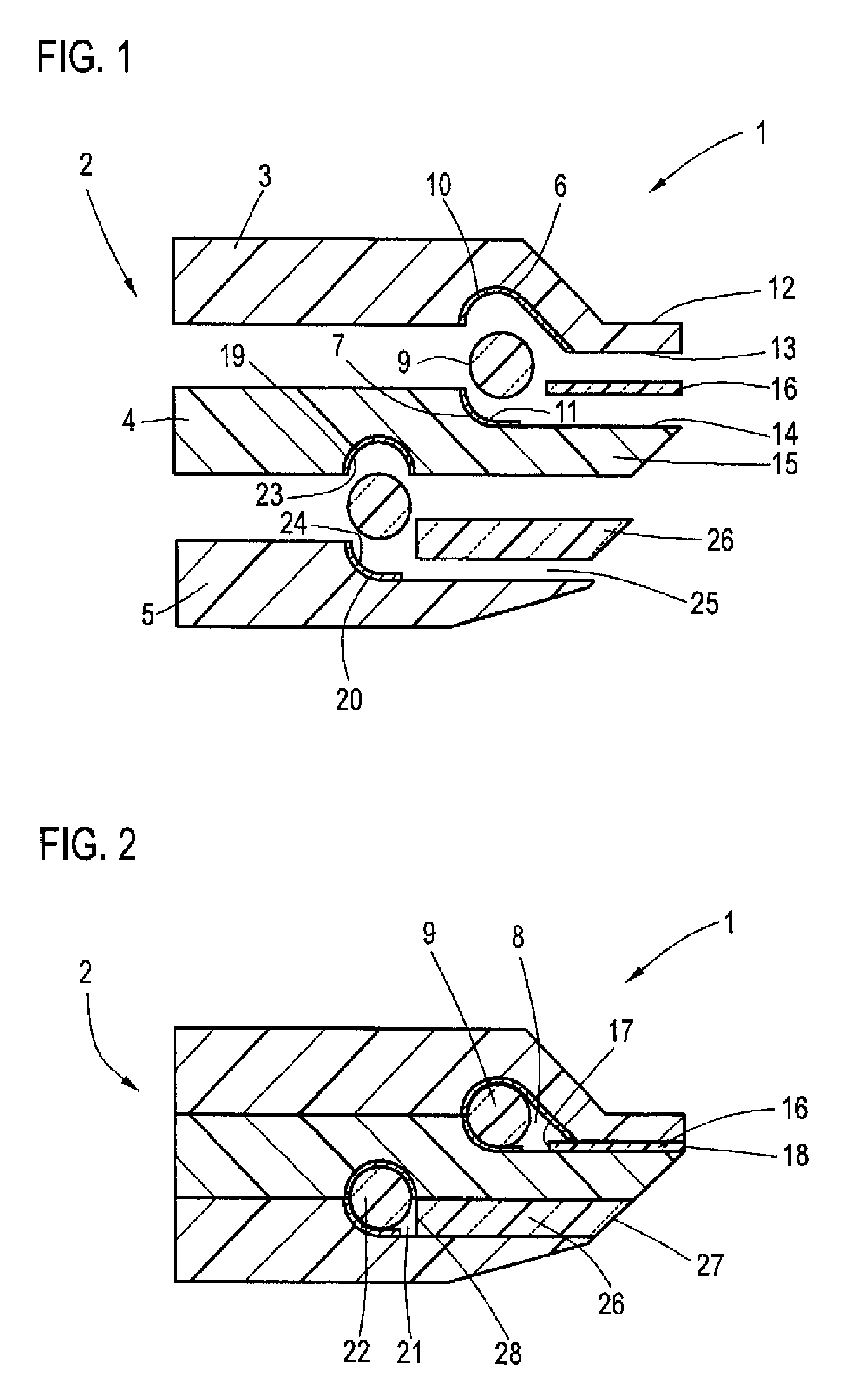
[0009]The present invention resolves prior art problems by providing a three-part housing which in order to generate a line light is elongated and of such a shape to correspond to the contour to be emulated and the contour to be framed by the generated light line. The first receiving space of the housing accommodates the first light conductor, with light being projected into this light conductor on one end and being extracted to the side. Disposed in parallel relationship to the first light conductor is the plastic film strip which is held between the edges of the first and second housing parts and terminates flush with these housing parts. The plastic film strip is transparent for light being emitted from the first light conductor. As the film strip extends parallel to this light conductor, emitted light from the light conductor is thus projected into a narrow end face of the film strip. Light exits from the other narrow end face which is flush-mounted between the narrow marginal regions of the first and second housing parts. This narrow end face thus forms the sole light emitting zone that defines the light strip. The thickness of the film strip can be made significantly smaller than the light conductor diameter so that realization of a much narrower light strip is possible. As a result, the contour lighting can be made very subtle to highlight even smaller structures in a pleasing look and can be easily integrated even when the available installation space is tight.
[0010]A combined ambient lighting is also provided and realized using the third housing part, with the second light conductor which is arranged in the second receiving space providing the ambient light. Light is hereby emitted via the gap between the second and third housing parts to the outside and thus into the room or surroundings. Also the ambient light is virtually “elongated”, with the second light conductor extending in parallel relationship to the first light conductor, and also with the gap extending in parallel relationship to the light exit line. Overall, the combined lighting device is of compact design and suitable for producing a contour illumination as well as an ambient illumination.
[0013]According to another advantageous feature of the present invention, the film strip may be dyed. In this way, there is the option to emit a colored contour illumination. Thus, generation of a red, yellow or green contour illumination line becomes possible even though white light is projected into the light conductor as initial light.
[0014]According to another advantageous feature of the present invention, the first and second housing parts may have terminal support surfaces, with the film strip being received between the support surfaces. In this way, the film strip can be securely fixed and integrated in the housing. The support surfaces provide a sufficiently large area for establishing a secure and firm fixation of the film strip. Advantageously, the support surfaces adjoin the receiving space. As a result, the film strip can be placed in immediate proximity to the first light conductor.
[0018]The marginal region of the housing where the strip with its light exit end face is arranged can be configured in a narrowest possible way by making the marginal region as small as possible through inwardly recessing one or more housing parts. In this way, the marginal region of the housing can be designed extremely narrow, especially when all housing parts are inwardly recessed. As a result, the marginal region has an overall thickness in the range of few millimeters so that the housing remains inconspicuous even when integrated in the object whose contour should be highlighted.
[0019]According to another advantageous feature of the present invention, a diffuser disk may be arranged in the gap. As a result, ambient light can be dispersed over a wide range into the room. Advantageously, the diffuser disk is clamped or bonded between the third housing part and the second housing part. The diffuser disk may also be dyed so as to produce a colored ambient light, when white light is projected into the second light conductor.

Problems solved by technology

Such a broad light strip is however in some cases undesired for optical reasons as the object to be highlighted is fairly small so that such a broad light strip would virtually be overdimensioned, or for structural reasons because it may not be possible to install such a broad light strip.

Method used


Image

  • Lighting device
  • Lighting device

Examples


Embodiment Construction

[0026]Throughout all the figures, same or corresponding elements may generally be indicated by same reference numerals. These depicted embodiments are to be understood as illustrative of the invention and not as limiting in any way. It should also be understood that the figures are not necessarily to scale and that the embodiments are sometimes illustrated by graphic symbols, phantom lines, diagrammatic representations and fragmentary views. In certain instances, details which are not necessary for an understanding of the present invention or which render other details difficult to perceive may have been omitted.

[0027]Turning now to the drawing, and in particular to FIG. 1, there is shown a schematic, exploded sectional view of a lighting device according to the present invention, generally designated by reference numeral 1. The lighting device 1 includes a housing 2 comprised of first, second, and third housing parts 3, 4, 5 which are made advantageously of plastic. It will be unde...


PUM


Abstract

A lighting device includes a housing having first and second housing parts to define a first receiving space there between, and a third housing part arranged on the second housing part to define an open gap. The third housing part defines with the second housing part a second receiving space in which a first light conductor is arranged. A plastic film strip is arranged between edges of the first and second housing parts and is transparent for light emitted by the first light conductor, with the emitted light being projected into one end face of the film strip and extracted from another end face of the film strip. The film strip is sized to terminate flush with the first and second housing parts. Arranged in the second receiving space is a second light conductor which emits light through the gap.

Description

CROSS-REFERENCES TO RELATED APPLICATIONS[0001]This application claims the priority of German Patent Application, Serial No. 10 2012 005 398.3, filed Mar. 16, 2012, pursuant to 35 U.S.C. 119(a)-(d), the content of which is incorporated herein by reference in its entirety as if fully set forth herein.BACKGROUND OF THE INVENTION[0002]The present invention relates, in general, to a lighting device, and more particularly to a combined contour and ambient lighting device for a motor vehicle.[0003]The following discussion of related art is provided to assist the reader in understanding the advantages of the invention, and is not to be construed as an admission that this related art is prior art to this invention.[0004]Lighting devices come in various types and shapes to illuminate a space or to identify or highlight certain articles or objects. These lighting devices are oftentimes referred to as contour lighting as they accent the shape and contour of an object being highlighted. Contour ...

Claims


Application Information

Patent Timeline
Patent Type & Authority Patents(United States)
IPC IPC(8): F21S8/10B60Q3/00B60Q3/02F21V8/00F21W106/00
CPCG02B6/0035B60Q3/004B60Q3/0289F21S48/00G02B6/001B60Q3/64B60Q3/78
Inventor PFEIL, MARCUSTOVAR, JOHANNESMAURER, JURGENMOHOS, RICHARD
Owner AUDI AG
Why Eureka
Try Eureka