Zone control of tool temperature

a tooling system and temperature control technology, applied in the direction of manufacturing tools, ceramic shaping apparatus,auxillary shaping apparatus, etc., can solve the problems of increasing production time and cost, increasing the difficulty of adjusting the temperature of the tooling, so as to reduce the viscosity of the resin and reduce the performance of one heater

Active Publication Date: 2015-05-19
SURFACE GENERATION
View PDF21 Cites 4 Cited by
  • Summary
  • Abstract
  • Description
  • Claims
  • Application Information

AI Technical Summary

Benefits of technology

[0029]In one embodiment the method comprise sensing a material property of said article material prior to commencement of the moulding process and supplying a signal indicative of said property to said controller prior to commencement of the moulding process, the controller modifies the control of said heating and cooling means during the moulding process in response to said material property sensed prior to commencement of the moulding process. In this manner the control can be modified to take into consideration differences material properties between batches of material. In another embodiment the article is manufactured by resin transfer moulding and the tool zones are sequentially heated from the point of resin injection in the direction of resin flow so as to elevate the mould temperature as the leading edge of the resin flow passes there over thereby reducing the viscosity of the resin at the resin / perform interface as it flows into the tool. The tool zones can be heated prior to the leading edge of the resin flow arriving there in a manner that when the resin passes the tool zone the tool surface temperature has already peaked and is starting to cool.
[0030]The tool zones may be user defined or may be automatically defined by the system. In one embodiment the controller of the system monitors the performance of the tool zones and if it is not possible for the controller to heat the tool zones to the required temperatures then it may redefine the tool zones. If for example the performance of one heater was to reduce due to malfunction, the tool zones could be redefined to include another heater within the same tool zone as the underperforming heater. Where multiple heaters are used they are preferably split between different phases of a three phase electric supply. Furthermore the controller controls the use of the heaters to ensure that a situation does not occur when a significantly unbalanced power draw is placed on any one single phase of the electricity. This may, for example include using heaters when they are not strictly needed. For example when a zone is desired to be cooled the heater associated with it could be periodically pulsed to place a small load on its electricity phase. As the fluid flow will still be below the temperature of the tool cooling will still occur albeit at a slower rate on account of the slightly increased temperature due to the pulsing of the heater. Such methods can assist in balancing the electricity supply used in the invention.
[0031]To assist in the balancing of the current the tooling system may be provided with two different levels of cooling, for example by switching between a high coolant flow and a low coolant flow. The high coolant flow could be used when extreme cooling is needed or could be used in combination with the use of the heaters as described above to effect cooling when the heaters are powered or partially powered without loosing cooling power compared to the lower normal coolant flow rate.

Problems solved by technology

When materials such as metals are used, the article can be treated after it comes off the tool or mould, for example by heat treating and quenching, to control the material properties, however these processes are lengthy and increase production time and cost.
When polymer materials are moulded, in particular thermosetting resins, which may also contain a filler, the finished article can not usually be treated by a secondary process to control its structural properties after it comes off the tool.
When using tools to produce articles that have a thick or, in particular, a variable thickness the problems associated with variance in material properties of the finished product are further compounded by variance in heat loss from the different thickness sections.
When thermosetting resins are used further complications arise by virtue of the exothermic nature of the process of curing / cross linking.
Furthermore autoclaves are notoriously energy inefficient and require large areas to accommodate their footprint which is typically much larger then the actual tool for the article.
Even though the different material properties arising from current tooling systems may, to some extent, be predictable it is not controllable.
In many instances, the design of articles, in particular those to be moulded out of thermosetting polymers, is compromised between an ideal design and a design that is practical to process.
A further problem with current moulding techniques, and particularly associated with autoclaves is that they are not controllable so as to vary the material properties of the articles they produce.
For example if a thermoplastic, e.g. PEEK, part of varying thickness were required that had thicker sections required to have a high crystallinity to impart strength and thinner sections having a lower crystallinity to impart flexibility, then current technologies are not effective in creating such a part in a single moulding process.

Method used


Image

  • Zone control of tool temperature
  • Zone control of tool temperature
  • Zone control of tool temperature

Examples


Embodiment Construction

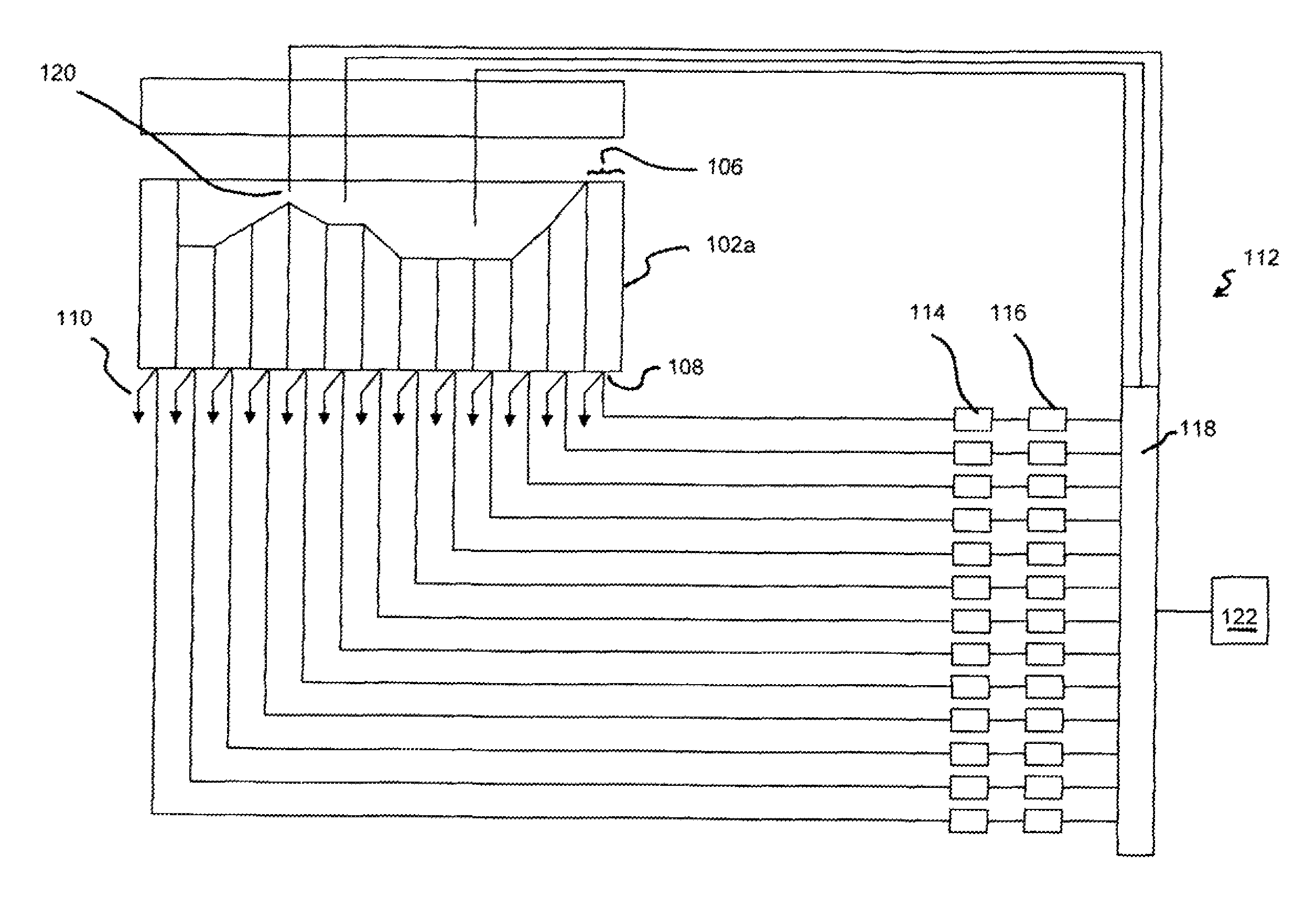
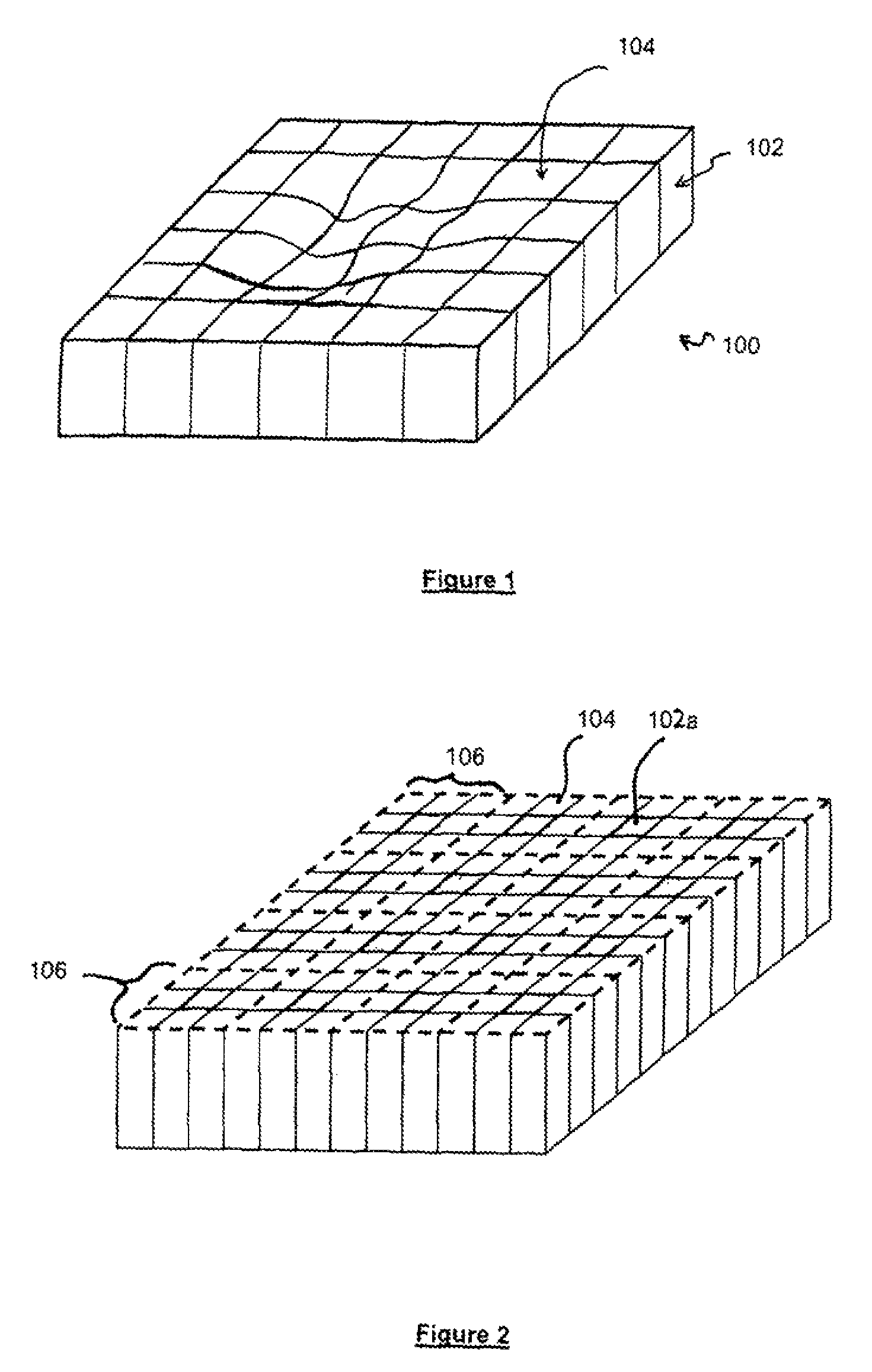
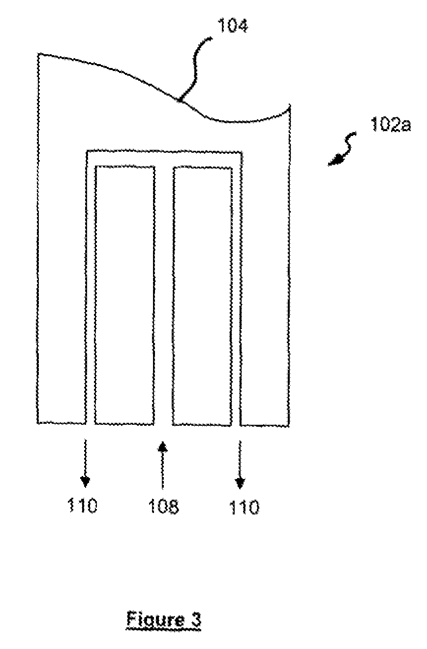
[0043]Referring to FIGS. 1 and 2 a tool 100 is shown comprising a plurality of tool pins 102 each having a surface 104 on a tool face which may be flat or which may have a contoured surface. The tool surface is divided into a plurality of tool zones 106, each zone comprising one or more tool pins. In the example shown in FIG. 2 each zone 106 is a 3×3 array of tool pins 102. The tool surface 104 of FIG. 2 is shown as being flat for illustration purposes only and would, in use, have a contoured / shaped tool surface. Each tool zone 106 has at least one heated / cooled pin 102a (see FIG. 3) associated therewith. The heated / cooled pin may be a single pin or where, each tool zone 106 comprises more than one tool pin 102, separate heated and cooled pins can be used. By controlling the application of heat and cooling to the tool zones 106 the transfer of energy into and out of an article being made in the tool 100 can be locally controlled at specific times during, the moulding process. As is ...


PUM

PropertyMeasurementUnit
temperatureaaaaaaaaaa
dielectric constantaaaaaaaaaa
ultrasonic absorption/transmissionaaaaaaaaaa

Abstract

A tool system for moulding an article is provided which comprising a tool (100) having a tool surface (104) for forming an article, the tool surface comprising a plurality of tool zones (106). Heating and cooling means (102a) are independently associated with at least some of said tool zones (106). A control means is adapted to control the heating and cooling means (102a) to individually heat or cool the tool zones (106) having heating and cooling means (102a) associated therewith so as to regulate the heat transfer into and out of the article at each tool zone (106) at any particular time throughout the moulding process.

Description

BACKGROUND[0001]This invention related to a heated tooling system, in particular to a heated tooling system for increased control of material properties of an article made in said tooling system.[0002]Many materials are moulded using a variety of moulding tools. It is well known in some industries, for example in the metal casting industry, that the rate and temperature at which a material solidifies affects the material properties of the article. This effect usually takes place on a microscopic scale and may for example include such characteristics as the proportion of amorphosity or crystallinity in the final product. When materials such as metals are used, the article can be treated after it comes off the tool or mould, for example by heat treating and quenching, to control the material properties, however these processes are lengthy and increase production time and cost.[0003]When polymer materials are moulded, in particular thermosetting resins, which may also contain a filler,...

Claims


Application Information

Patent Timeline
Patent Type & Authority Patents(United States)
IPC IPC(8): B29C33/02B29C33/04B29C33/30B29C35/00B29C35/02B29C37/00
CPCB29C35/0288B29C33/02B29C33/046B29C33/302B29C33/306B29C35/007B29C35/0294B29C2037/90B29C2037/903B29C2037/906
Inventor HALFORD, BEN
Owner SURFACE GENERATION
Why Eureka
Try Eureka