Combined lighting device with an integrated dimming control system

a dimming control system and lighting control technology, applied in the field of lighting devices, can solve the problems of increasing the complexity and cost of installation, and the installation cost of existing lighting control systems that are multi-zone multi-scenes, and achieve the effect of dramatic change in the mood of the room

Active Publication Date: 2015-05-19
DOLAN DESIGNS
View PDF21 Cites 42 Cited by
  • Summary
  • Abstract
  • Description
  • Claims
  • Application Information

AI Technical Summary

Benefits of technology

[0010]Another aspect of the invention is to be able to offer a lighting device that has multiple scenes with layered lighting effects such as general area lighting, task lighting, grazing and accent lighting that can all be pre-programmed and easily selected.
[0016]In most dining rooms there is usually only one single gang box controlling a chandelier. With this invention, the existing switch is easily removed and replaced with a remote control with 4-6 different actuators from which to select different scenes, as well as an on / off control. There are no multi-zone multi-scene master controls that are able to fit into an industry standard single gang decora switch plate and box, so remotely installing the master dimming control in the chandelier or lighting device is a desirable advantage. A wall-mounted remote or a hand-held remote could use a touch screen or buttons as actuators that are commonly used in a smart phone or security controller along with any other known actuator.
[0025]The invention enables a single lighting device that incorporates several lighting effects, such as general area lighting, down lighting, accent lighting, grazing, and indirect lighting and a plurality of up lighting each wired to different zones so that each type of lighting effect could be mixed to create different scenes of lighting.

Problems solved by technology

Existing lighting control systems that are multi-zone multi-scene are expensive to install and usually require a lighting designer or lighting specialist to create the lighting design.
In many installations in existing homes it is necessary to cut out sections of the ceiling drywall or lath and plaster to run wiring, which adds greatly to the complexity and cost of the installation.

Method used


Image

  • Combined lighting device with an integrated dimming control system
  • Combined lighting device with an integrated dimming control system
  • Combined lighting device with an integrated dimming control system

Examples


example 1

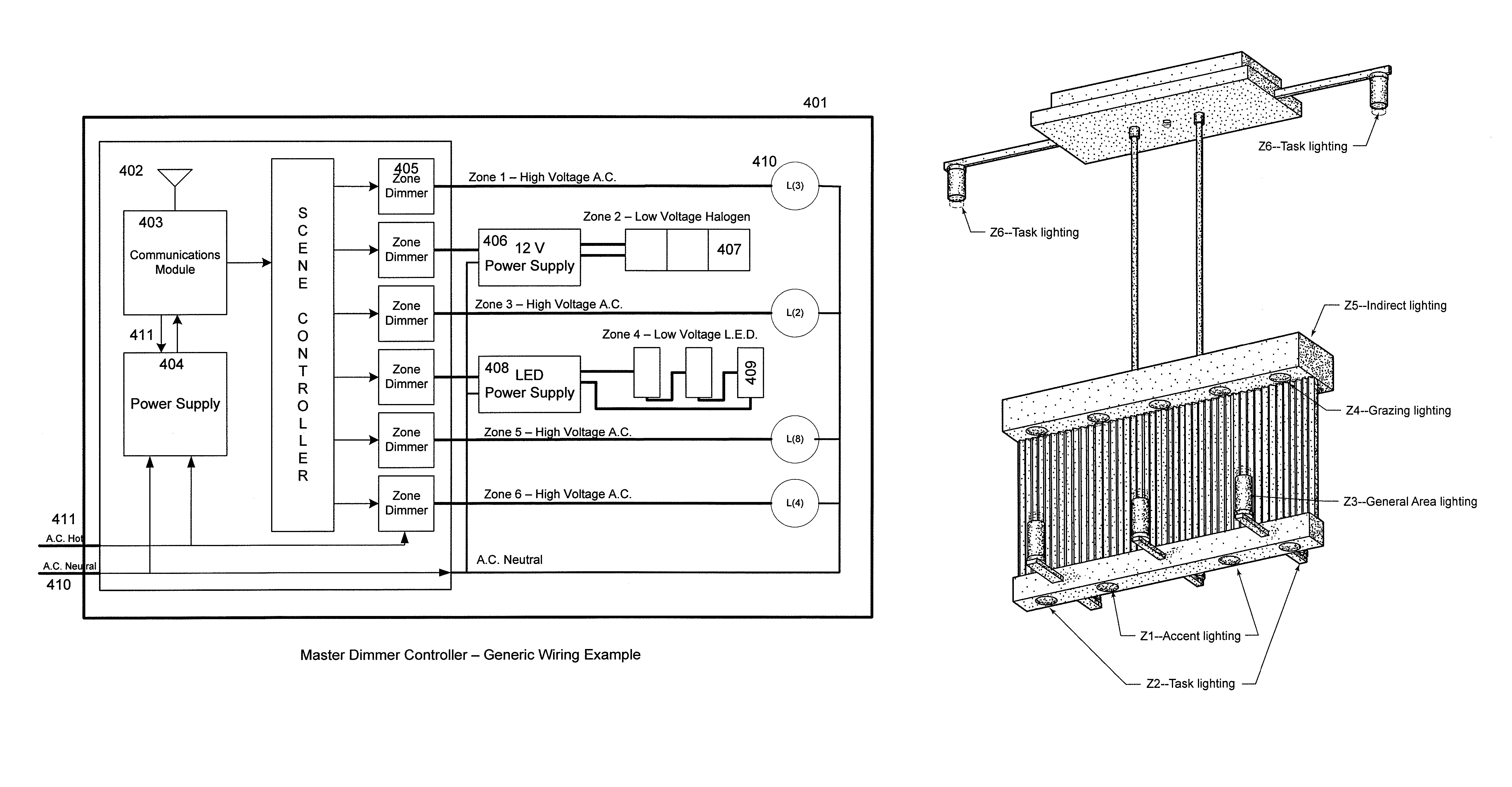
[0090]FIGS. 17-22 show a modern-style chandelier incorporating six zones of lighting fixtures. Each of these zones is connected to and controlled by a master dimming controller, as previously described, mounted in the ceiling base. Zone 6 Task lighting is powered from the controller through A.C. power lines extending through the base and the oppositely extending arms to the fixtures. Zones 1 through 5 are powered by separate lines extending from the master dimming controller in the base through tubes that suspend the main body of the chandelier from the base. The main body of the chandelier in this example has upper and lower cross beams interconnected by a web. Zones 1 and 2 are downwardly directed lamps, which may be aimable, to provide accent lighting and task lighting. Zone 3 has six upward-directed lamps to provide general area lighting. The upper bar includes ten Zone 4 lamps, best seen in FIG. 22, that are downward directed and spaced close to the web to providing grazing lig...

example 2

[0091]FIGS. 23-28 show a ceiling fan lamp incorporating five zones: four zones of lighting fixtures (Zones 1-4) plus one zone (Zone 5) for the fan motor. Zones 1, 2 and 3 utilize low voltage lighting fixtures, which can be LEDs or high intensity lamps to provide different illumination effects, and are controlled by low voltage outputs from the master dimming control. Zone 4 is a high voltage zone to provide general illumination from an incandescent lamps. Zone 5 is the fan motor circuit, for which the master dimming controller can provide speed and direction controlled power signals.

example 3

[0092]FIGS. 29-39 show another example of a chandelier with a master control dimming system. In this particular embodiment of my invention, the dimming system is in the base or canopy of the light fixture mounted to the fire-plate. In this embodiment, the chandelier uses the Echelon power line Smart Transceivers to communicate between the chandelier and a remote control dimmer, mounted in a wall box. A wireless handheld remote can also communicate with the master dimming control mounted within the canopy. (It is understood that other companies in addition to Echelon offer power line technology.)

[0093]In FIG. 29, this chandelier has 8 different zones. Each zone performs a different lighting effect such as in zone 1 general area lighting; in zone 2 indirect lighting near the top of the body of the chandelier; in zone 3 indirect lighting behind the decorative badges around the center decorative ring; in zone 4 task lighting; in zone 5 accent lighting under the chandelier's decorative r...


PUM


Abstract

A multi-scene, multi-zone lighting device includes a support structure supporting multiple lighting zones, an ensemble of the zones defining a lighting scene. A master dimming control built into the support structure has a power input line and multiple dimmers. The zones are coupled to the dimmer output lines to receive a controlled setting from the corresponding dimmer. A remote control device communicates with the master dimming control, and has a memory for storing settings for the multiple zones and a user interface for a user to select a stored setting for each zone or a scene composed of multiple zones. Settings can be prestored or programmed by the user. The master dimming control includes a controller responsive to receiving the set of settings to set the controlled setting of the corresponding dimmer for each zone in the selected scene to conform the zones to the settings in the selected scene.

Description

CROSS REFERENCE TO RELATED APPLICATION[0001]This application claims the benefit of U.S. provisional patent application Ser. No. 61 / 596,101, filed Feb. 7, 2012, herein incorporated by reference.FIELD OF THE INVENTION[0002]The present invention generally relates to a lighting device with a master dimming control system enclosed with the lighting device. More particularly, the lighting device has a plurality of lighting effects, scenes and zones controlled by one or more remote control switches.BACKGROUND OF THE INVENTION[0003]Existing lighting control systems that are multi-zone multi-scene are expensive to install and usually require a lighting designer or lighting specialist to create the lighting design. These lighting systems are not installed just to raise and lower the lighting in a room but rather they are installed so they will create a dramatically different lighting effect with each of the different actuators on a remote, wall control, or master control. In order to install ...

Claims


Application Information

Patent Timeline
Patent Type & Authority Patents(United States)
IPC IPC(8): H02J3/00H05B41/36H05B37/02G05F1/00H05B39/04
CPCH02J3/00H05B37/02H05B37/0245H05B47/175H05B47/19H05B47/195F21S8/06F21V21/008H05B35/00
Inventor DOLAN, PATRICK, S.
Owner DOLAN DESIGNS
Why Eureka
Try Eureka