Power generator
a power generator and power input technology, applied in the direction of electric generator control, couplings, fluid couplings, etc., can solve the problems of reducing the efficiency, and therefore the viability of the system, and generating power input is the problem of the system, and achieve the effect of increasing efficiency
- Summary
- Abstract
- Description
- Claims
- Application Information
AI Technical Summary
Benefits of technology
Problems solved by technology
Method used
Image
Examples
third embodiment
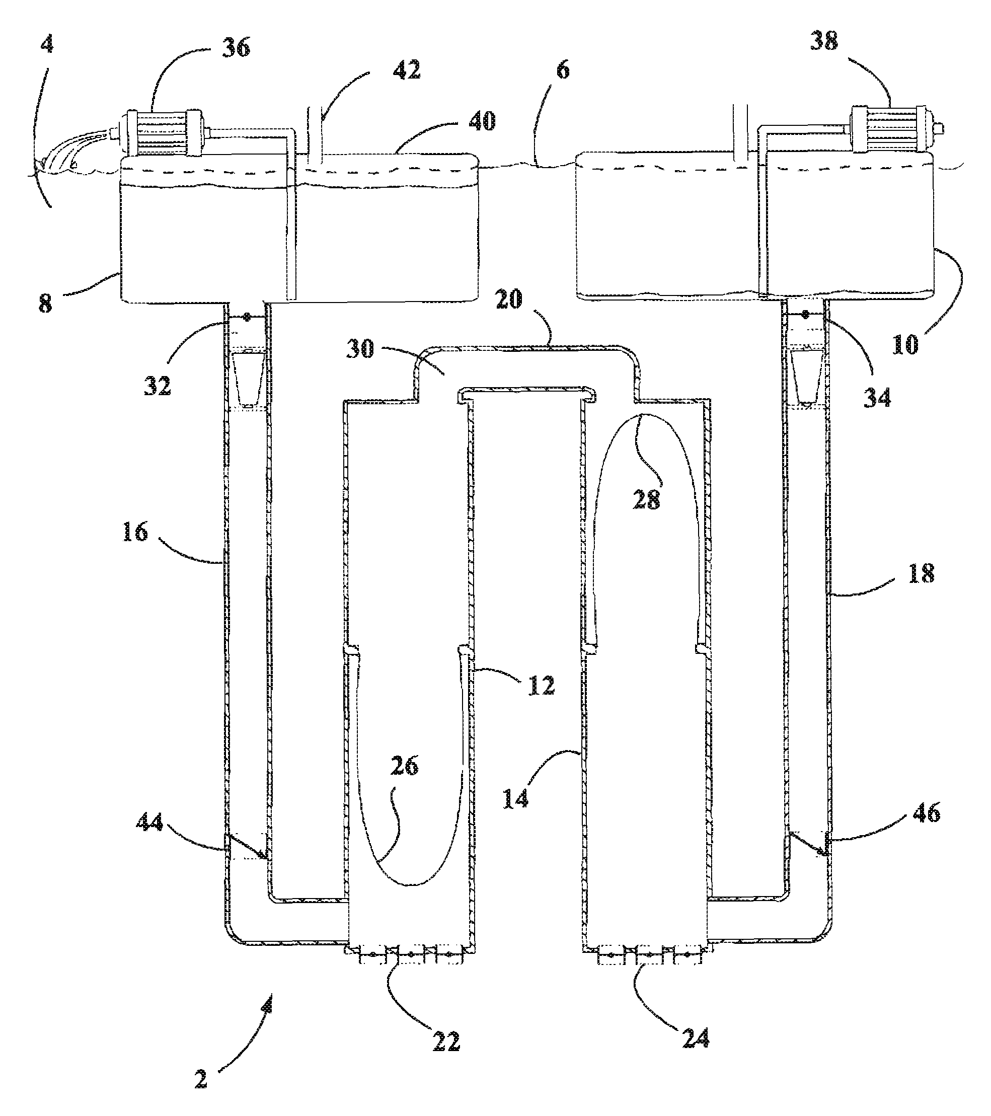
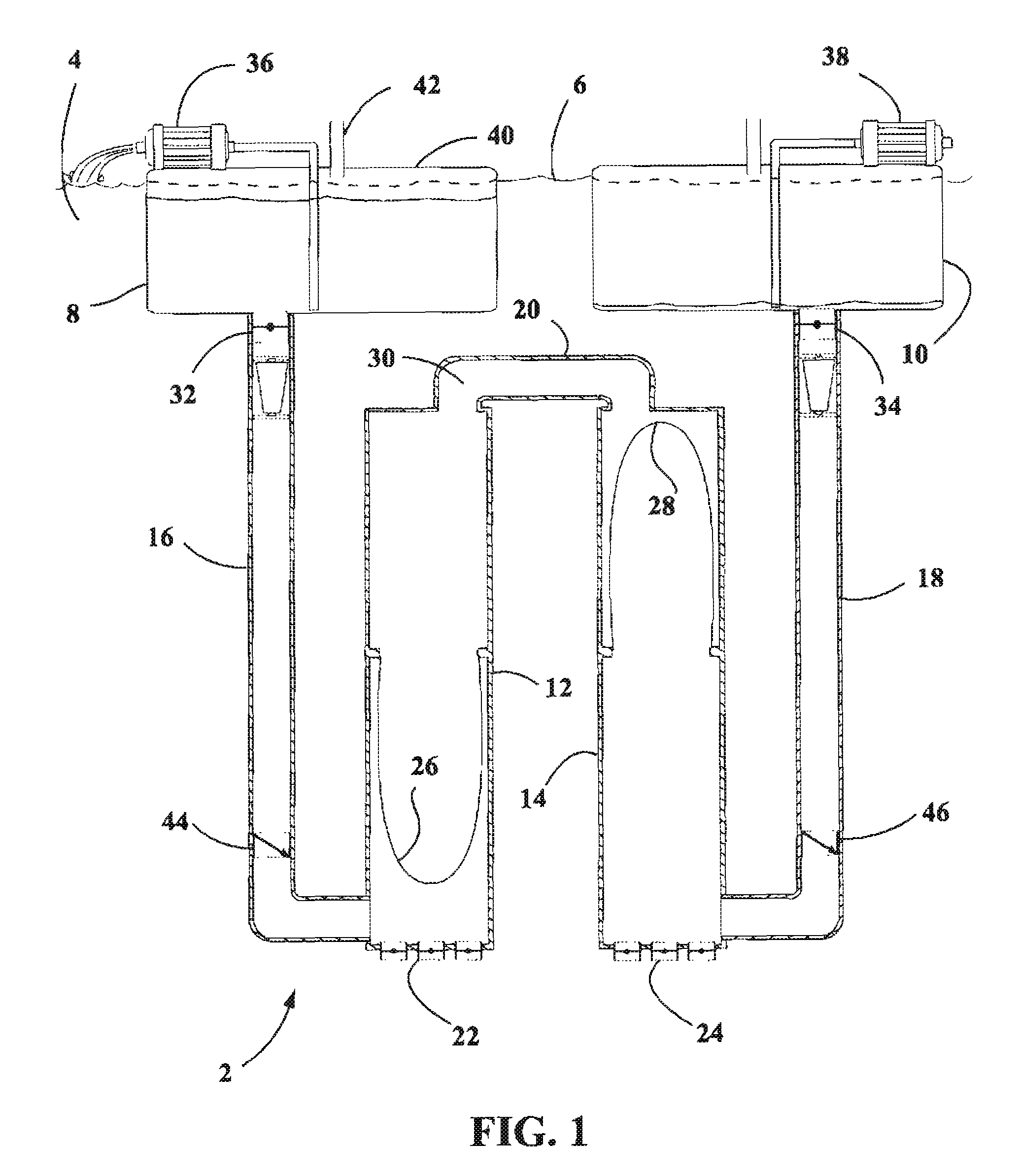
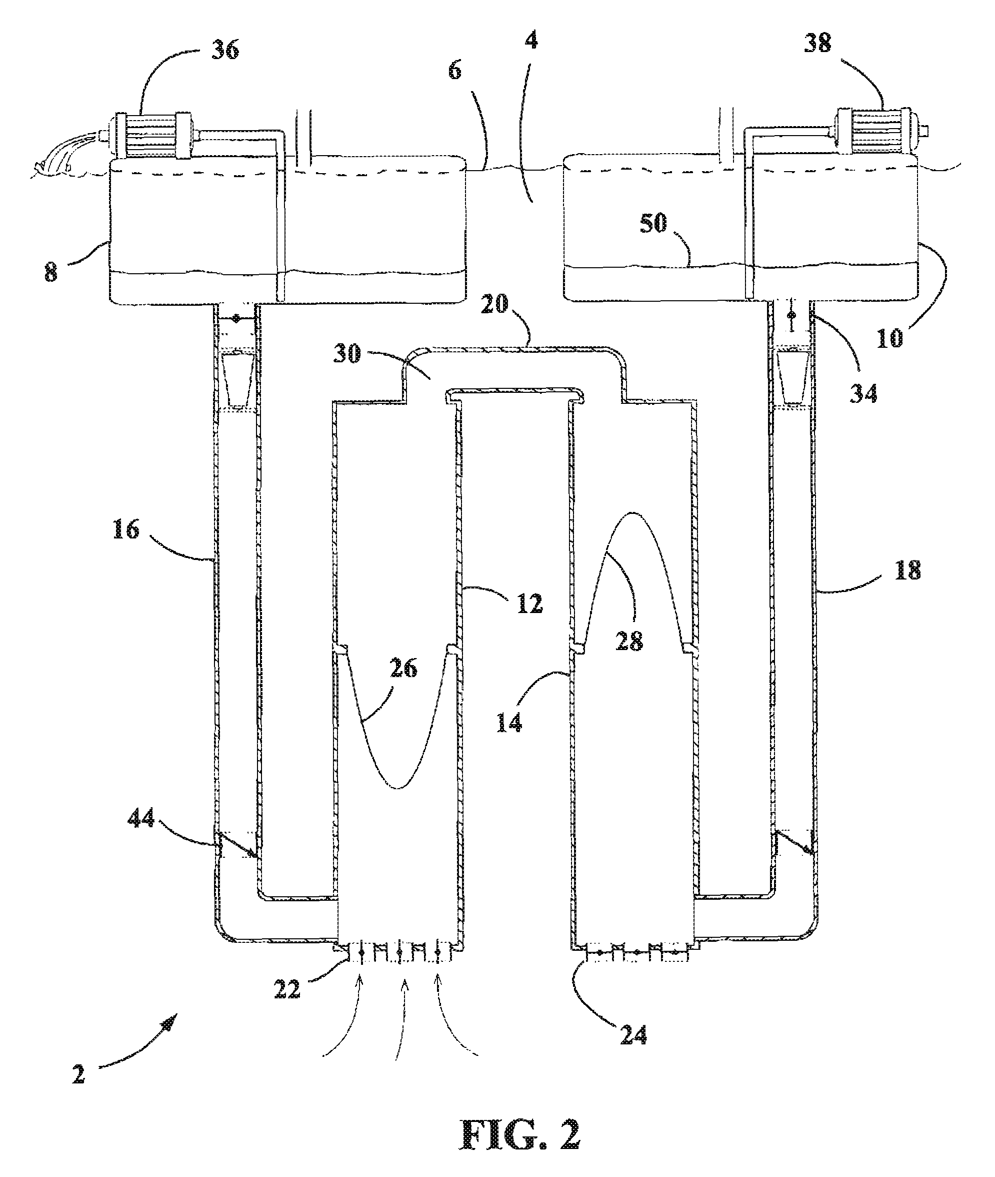
[0089]the apparatus depicted in FIGS. 8-11 utilizes pontoons contained within pontoon chambers to enhance and augment the power derived from the water flowing through the system 202. For relatively little power investment, the pontoons enable the system 102 to greatly augment the work performed by the connecting rods external to the 102.
[0090]FIG. 8 depicts an arrangement similar to that shown in FIGS. 5-7, but with modifications to the regions between the first 216 and second 218 evacuation tubes. The movable extremes of the constant volumetric flow region 230 are rigid plates affixed to and capping the end of a first 326 and second 328 upper pontoon chamber coil tube. As the constant volumetric flow region shifts from one pontoon chamber to the other, the first 326 and second 328 upper pontoon chamber coil tubes alternate in their expansion and contraction, maintaining a constant volume of water within the coil tubes and connecting pipe 220. As in FIGS. 5-7, the first 212 and seco...
exemplary embodiment 2000
[0179]Finally, FIGS. 34-35 illustrate that vertical and horizontal positioning may be interchangeable in the given systems, wherein orientation is not meant to be limiting. In this exemplary embodiment 2000, the constant volumetric region 2002 is defined at movable boundary ends 2004 and 2006 connected by rod 2008. The region 2002 can be air or water filled, and is preferably provided with one or more baffles 2010. The baffles 2010 may be further provided with turbines or other such generators, such as 2012 and 2014. Note that, in this embodiment turbines 2012 allow flow in one direction, and turbines 2014 allow flow in the other. Less or more turbines can be used, in combination with bypass valves as an alternative, for instance. Finally, gate turbines 2016 are placed at the power chamber 2018 and 2020 inlets, which operate with the first 2022 and second 2024 return systems to cycle as previously described herein.
PUM
 Abstract
Description
Claims
Application Information
 - R&D
- Intellectual Property
- Life Sciences
- Materials
- Tech Scout
- Unparalleled Data Quality
- Higher Quality Content
- 60% Fewer Hallucinations
Browse by: Latest US Patents, China's latest patents, Technical Efficacy Thesaurus, Application Domain, Technology Topic, Popular Technical Reports.
© 2025 PatSnap. All rights reserved.Legal|Privacy policy|Modern Slavery Act Transparency Statement|Sitemap|About US| Contact US: help@patsnap.com


