Motion activated toilet bowl lighting device

a toilet bowl and motion technology, applied in the direction of electric discharge lamps, discharge tube/lamp details, incandescent screens, etc., can solve the problems of inconvenient or undesirable experience, bright lights may seem almost blinding, and the lights of the bathroom seem overly bright, etc., to achieve the effect of convenient use and inexpensive production

Inactive Publication Date: 2015-05-26
GLOW BOWL LLC
View PDF13 Cites 10 Cited by
  • Summary
  • Abstract
  • Description
  • Claims
  • Application Information

AI Technical Summary

Benefits of technology

[0007]A general object of this invention is to provide a motion activated toilet bowl lighting device that may be positioned on the rim of a toilet bowl having a light positioned toward the interior of the toilet bowl and that energizes the light when motion in the room is detected
[0010]Yet another object of this invention is to provide a motion activated toilet bowl lighting device, as aforesaid, that is easy to use and inexpensive to produce.

Problems solved by technology

Turning a light on when entering a bathroom in the middle of the night after being asleep or otherwise in a darkened room can be an uncomfortable or undesirable experience in that the bright lights may seem almost blinding.
In other words, the lights of the bathroom seem overly bright when a person's eyes have naturally adjusted to the darkness.
After using the toilet and turning off the lights, it may then be difficult to navigate back to bed in that the person's eyes must readjust to the darkness.
For these reasons, a person may choose not to turn the lights on at all when walking into a bathroom which leads to obvious difficulties of potentially stumbling over obstacles, finding the toilet, or actually using the toilet.
Although assumably effective for their intended purposes, the existing devices do not satisfy the need to energize a light situated in the toilet bowl when a person is detected entering the bathroom and then for de-energizing the light either when the person is detected leaving the bathroom or after a predetermined amount of time.

Method used


Image

  • Motion activated toilet bowl lighting device
  • Motion activated toilet bowl lighting device
  • Motion activated toilet bowl lighting device

Examples


Embodiment Construction

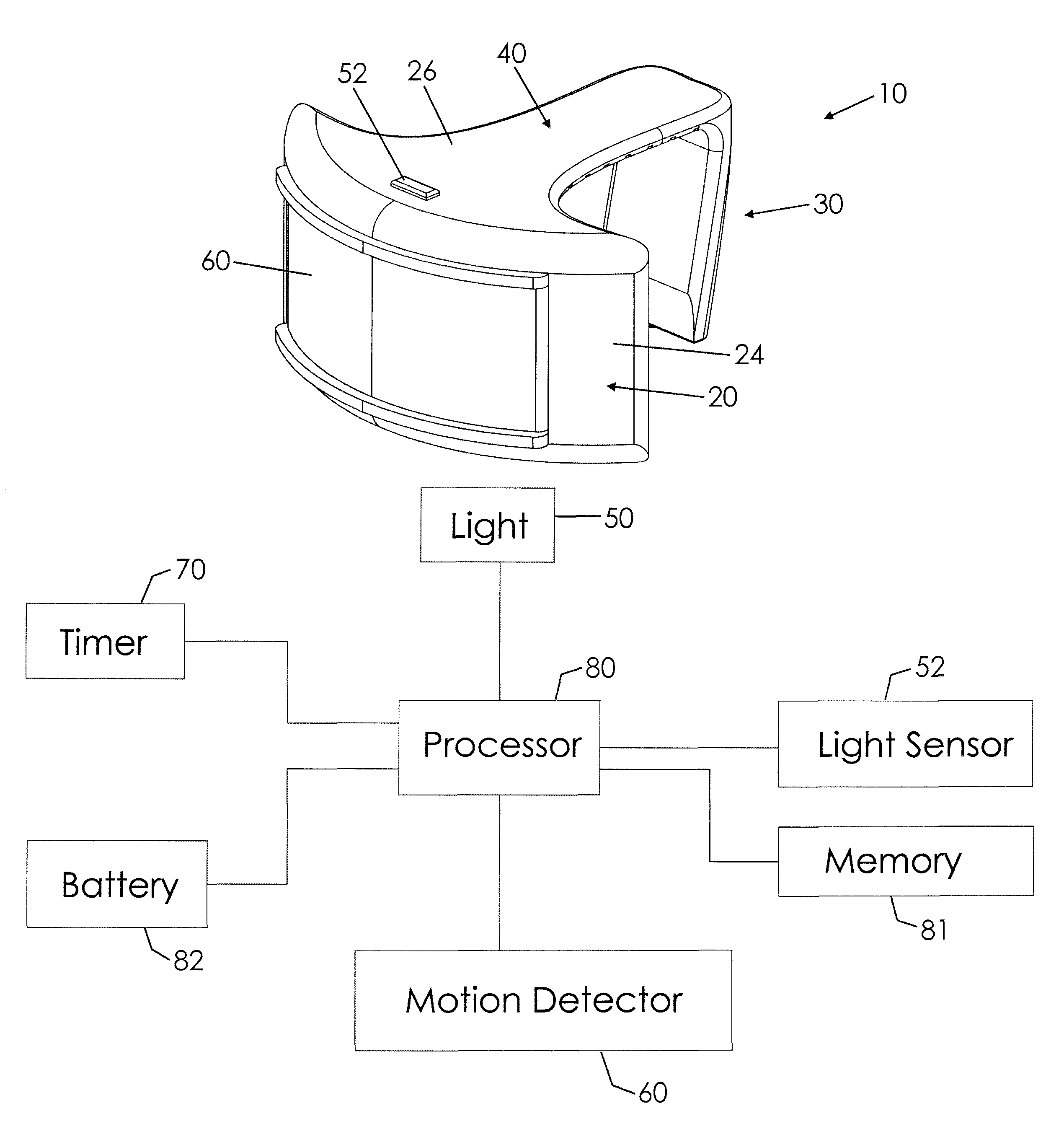
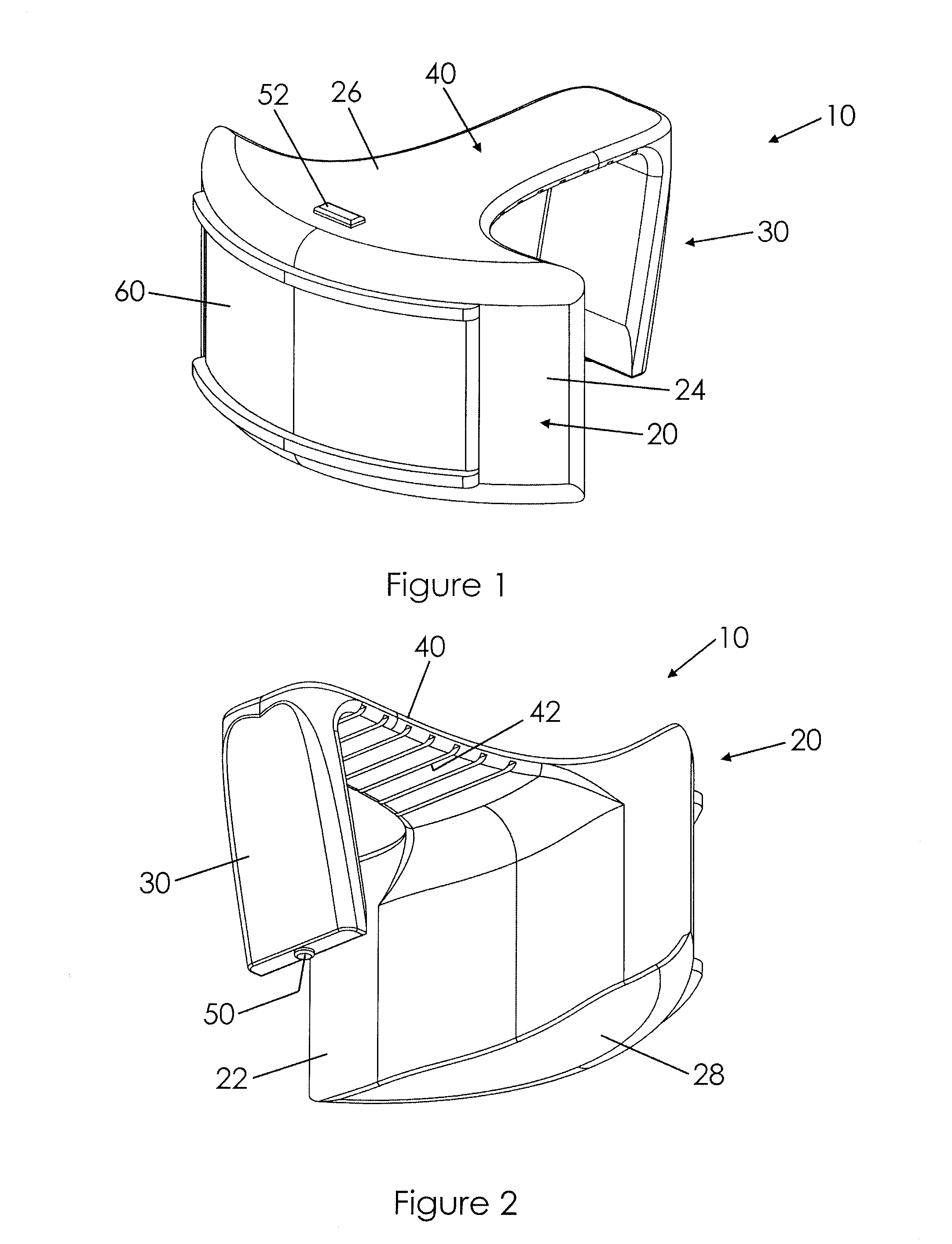
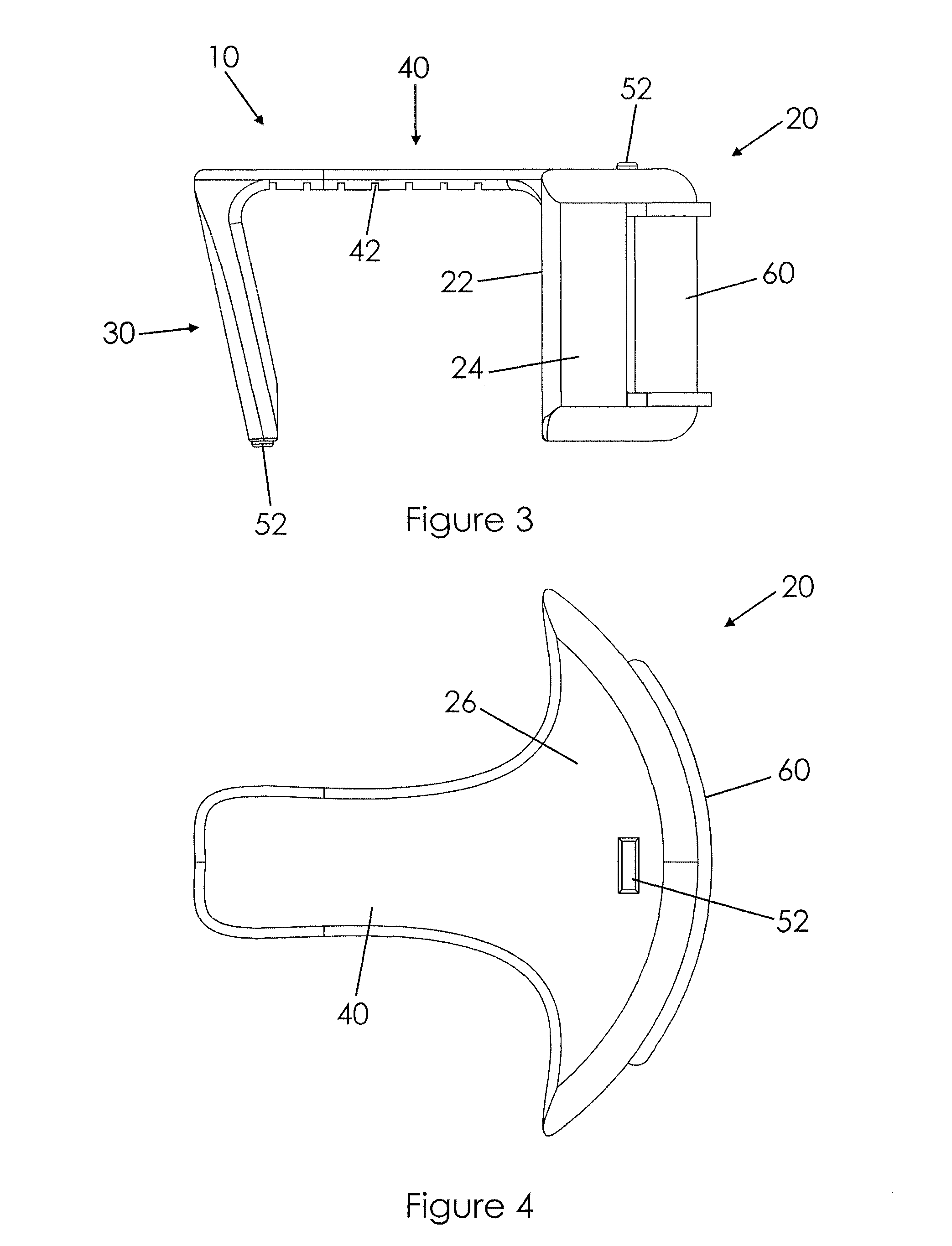
[0017]A motion activated toilet bowl lighting device according to a preferred embodiment of the present invention will now be described in detail with reference to FIGS. 1 to 6 of the present invention. The toilet bowl lighting device 10 includes a body member 20, an attachment arm 30, a bridge 40 connecting the body member 20 and attachment arm 30, a light 50, a light sensor 52, and a motion detection unit 60.

[0018]The body member 20 includes an inner wall 22 defining an inwardly annular or concave configuration that is complementary to an outwardly annular outer surface of a toilet bowl (not shown). The body member 20 also includes an outer wall 24 having a generally outwardly annular or convex configuration that is coupled to end edges of the inner wall 22 and extends outwardly therefrom. The body member 20 includes a top wall 26 and a bottom wall 28 that connect the inner 22 and outer 24 walls together. The walls collectively define an interior area. The body member 20 may inclu...


PUM


Abstract

A motion activated toilet bowl lighting device includes a body member having inner, outer, top, and bottom walls that define an interior area. The inner wall includes an inwardly annular configuration complementary to a toilet bowl rim outer surface. The lighting device includes an attachment arm displaced from the inner wall. A bridge connects the top wall to the attachment arm such that the inner wall, attachment arm, and bridge sandwich the toilet rim. A motion detector is positioned on the outer wall and a light is positioned on the attachment arm. A light sensor is positioned on the body member. A battery and timer are situated in the interior area. The light is energized when the light sensor detects lower than a predetermined amount of ambient light and when the motion detector detects movement, the light being de-energized when the timer expires.

Description

REFERENCE TO RELATED APPLICATIONS[0001]This non-provisional patent application claims the benefit of provisional application Ser. No. 61 / 521,943 filed on Aug. 10, 2011, titled Motion Activated Toilet Bowl Lighting Device.BACKGROUND OF THE INVENTION[0002]This invention relates generally to lighting devices and, more particularly, to a toilet bowl lighting device that is actuated upon detection of motion so long as the level of ambient light is below a predetermined level. In other words, the motion activated toilet bowl lighting device is configured to energize a light situated adjacent a toilet bowl when a person enters a bathroom while the bathroom light is off.[0003]Turning a light on when entering a bathroom in the middle of the night after being asleep or otherwise in a darkened room can be an uncomfortable or undesirable experience in that the bright lights may seem almost blinding. In other words, the lights of the bathroom seem overly bright when a person's eyes have naturall...

Claims


Application Information

Patent Timeline
Patent Type & Authority Patents(United States)
IPC IPC(8): H05B37/02
CPCH05B37/0227Y02B20/44Y02B20/40H05B47/115H05B47/11
Inventor ANDY, BRIAN R.BARBIERI, JEFF S.
Owner GLOW BOWL LLC
Why Eureka
Try Eureka