Substrate transfer apparatus

a technology of transfer apparatus and substrate, which is applied in the direction of pile separation, transportation and packaging, manufacturing tools, etc., can solve the problems of difficult to transfer a substrate to a target position, difficult to perform accurate operation with respect to a first substrate, and inability to accommodate such unexpected factors, etc., to achieve accurate and stable manner

Active Publication Date: 2015-06-09
YAMAHA MOTOR CO LTD
View PDF10 Cites 0 Cited by
  • Summary
  • Abstract
  • Description
  • Claims
  • Application Information

AI Technical Summary

Benefits of technology

[0007]The present invention has been made in consideration of the problems described above and an object thereof is to provide a technique that enables a substrate stopped at a first position to be transferred toward a second position and be stopped at the second position in an accurate and stable manner.

Problems solved by technology

Therefore, it is still difficult to perform accurate operation with respect to a first substrate in transferring to the target position.
In addition, unexpected factors may arise during substrate transfer such as an occurrence of belt deterioration or substrate slippage while a substrate is being transferred by a belt.
However, the apparatus described in JP Patent Publication No. 2009-27202 is unable to accommodate such unexpected factors.
Hence, it is difficult to transfer a substrate to a target position and positioning the substrate at the target position in a stable manner.

Method used


Image

  • Substrate transfer apparatus
  • Substrate transfer apparatus
  • Substrate transfer apparatus

Examples


Embodiment Construction

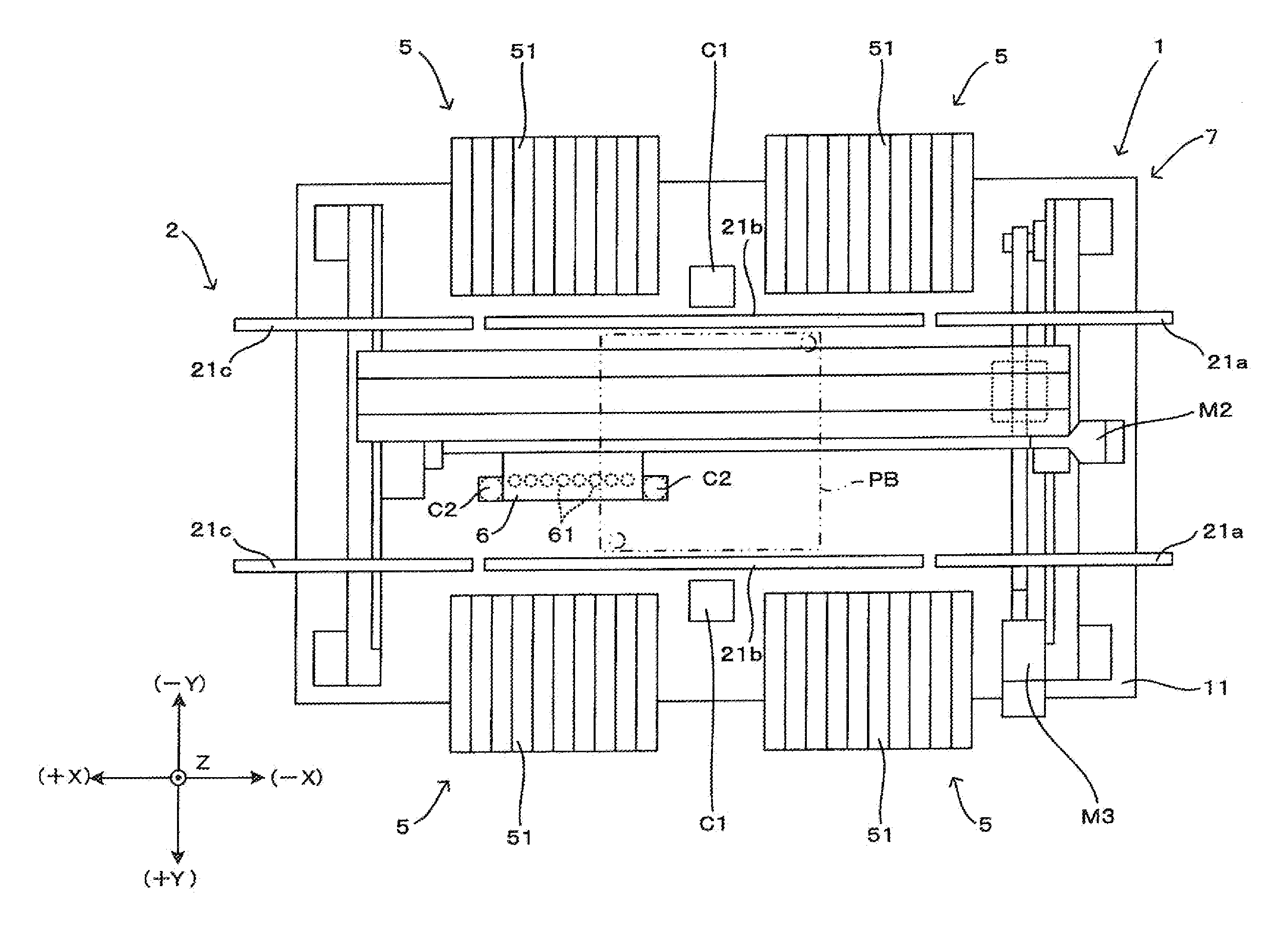
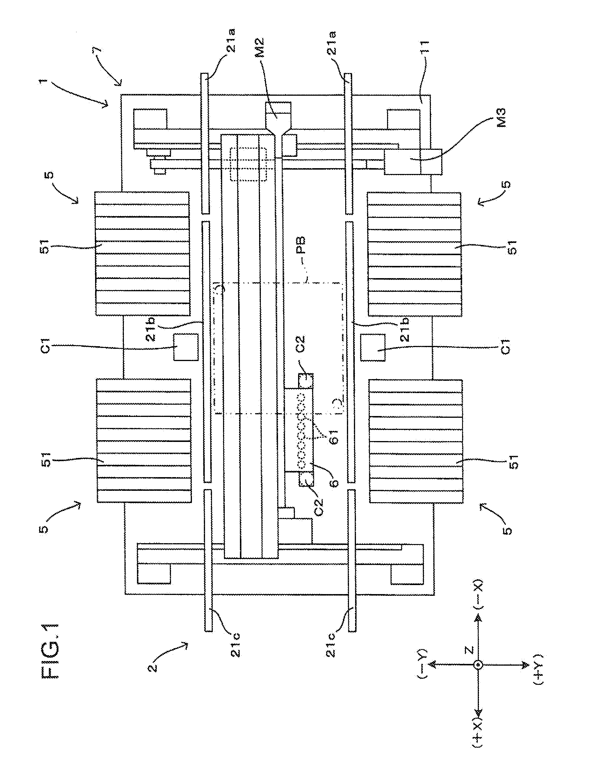
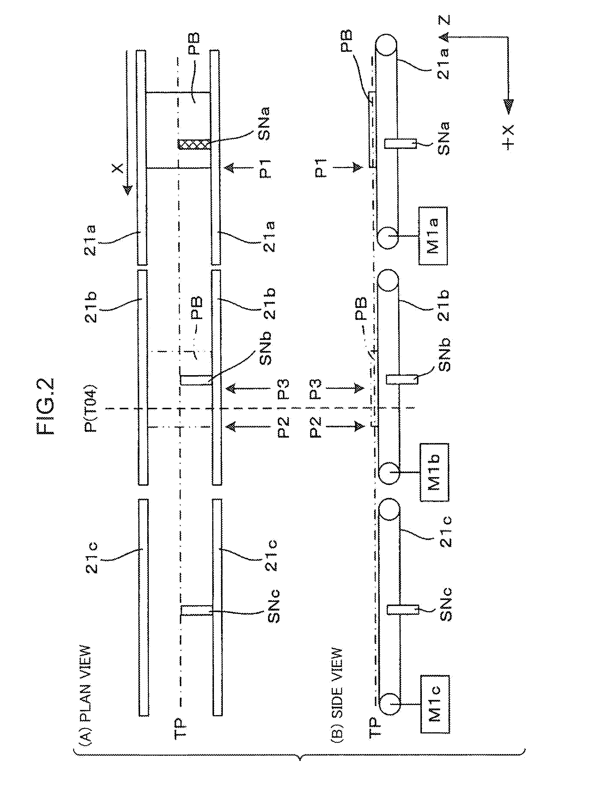
[0020]According to the present invention (substrate transfer apparatus and substrate transfer method), a substrate stopped at a first position will be transferred toward a second position along a substrate transfer path by substrate transfer means. The substrate is then detected at an intermediate position between the first position and the second position by detection means. A measuring step will be carried out to measure an intermediate position arrival time that is a time required for transferring the substrate from the first position to a detecting position where the substrate is detected. The intermediate position arrival time may vary in a case in which substrate transfer deviates from an acceleration / deceleration pattern set in advance occurs, or in a case in which an unexpected factor such as belt deterioration, substrate slippage, or the like occurs during the travels of the substrate from the first position to the substrate detecting position (the intermediate position bet...


PUM

PropertyMeasurementUnit
velocityaaaaaaaaaa
arrival timeaaaaaaaaaa
timeaaaaaaaaaa

Abstract

A substrate stopped at a first position is transferred toward a second position and is stopped at the second position in an accurate and stable manner. An intermediate position arrival time AT is measured while the substrate is being transferred from a substrate stop position toward a mounting work position, and a transfer status of the substrate (whether or not an unexpected factor has occurred) is assessed based on the intermediate position arrival time AT. Before the substrate reaches the second position, a deceleration pattern is controlled by altering a deceleration start timing T14 and the deceleration b in accordance with the intermediate position arrival time AT, thereby accurately stopping and positioning the substrate at the mounting work position. In this manner, under feed-forward control, the substrate can be stably transferred to the mounting work position.

Description

BACKGROUND OF THE INVENTION[0001]1. Field of the Invention[0002]The present invention relates to a substrate transfer apparatus and a substrate transfer method to transfer a substrate stopped at a first position toward a second position and to stop the substrate at the second position, and a surface mounter that mounts components on the substrate positioned at the second position by the substrate transfer apparatus.[0003]2. Description of the Background Art[0004]With a substrate processing system that mounts electronic components on a substrate, substrate processing apparatuses such as a printer, a print inspector, a surface mounter, a mount inspection apparatus, and the like are installed side by side along a transfer path. The respective substrate processing apparatuses perform desired processes according to a processing program on a substrate transferred along a substrate transfer path. As for a surface mounter, for example, a substrate transfer mechanism transfers a substrate to...

Claims


Application Information

Patent Timeline
Patent Type & Authority Patents(United States)
IPC IPC(8): B23P19/00H01L21/677H05K13/02H05K13/00H05K13/08
CPCH01L21/677H05K13/02H05K13/0061H05K13/08Y10T29/53174B65G49/06H05K13/04
Inventor UEKAWA, DAISUKEYAMADA, KAZUAKI
Owner YAMAHA MOTOR CO LTD
Why Eureka
Try Eureka