
Server and partition thereof

a server and partition technology, applied in the field of server and partition thereof, can solve the problem of difficulty in utilizing the remaining arrangement space for disposing of more half-height server units

Active Publication Date: 2015-06-09
WISTRON CORP
View PDF7 Cites 0 Cited by
  • Summary
  • Abstract
  • Description
  • Claims
  • Application Information

AI Technical Summary

Benefits of technology

[0005]The invention provides a server. A partition of the server is adapted to be mounted in a chassis and provide a fixing structure, which allows more server units to be arranged in the chassis.
[0006]The invention provides a partition. The partition is adapted to be mounted in a chassis and provide a fixing structure, which allows more server units to be arranged in the chassis.
[0014]In an embodiment of the invention, the partition further includes a first elastic component connected between the plate and the pivot component. When the structural interference between the stopping portion and the chassis is eliminated, the locking component moves from the second position to the first position by an elastic force of the first elastic component to disengage the first locking portion from the chassis.
[0017]In an embodiment of the invention, the server unit has a stopping element. When the server unit is located in the first space, the server unit is prevented from moving away from the accommodating cavity by a structural interference between the stopping element and the chassis. When the server unit is located in the second space, the server unit is prevented from moving away from the accommodating cavity by a structural interference between the stopping element and the partition.
[0021]Based on the above, the partition of the invention is adapted to be mounted in the accommodating cavity of the chassis and has the second fixing structure. Accordingly, the server unit may not only be fixed in the first space in the accommodating cavity by the first fixing structure of the chassis, but may also be fixed in the second space in the accommodating cavity by the second fixing structure of the partition. In this way, the arrangement space in the chassis is effectively utilized for arranging more server units. Also, variability and selectivity in number and position of the server units arranged in the chassis are enhanced. In addition, the locking component of the invention has the first locking portion and the stopping portion, and the partition has the pivot component pivoted between the plate and the locking component. Accordingly, when a user intends to assemble the partition, he / she may first place the partition in the accommodating cavity of the chassis, and then apply a force to the locking component to cause the locking component to move from the first position to the second position relative to the plate by rotation of the pivot component. At this moment, the first locking portion is locked to the chassis, and the structural interference is formed between the stopping portion and the chassis to position the locking component, thereby completing the assembly of the partition. When the user intends to detach the partition, he / she may eliminate the structural interference between the stopping portion and the chassis to reset the locking component from the second position to the first position. Accordingly, the first locking portion is disengaged from the chassis to allow the partition to be detached from the chassis. By using the above assembling and detaching methods, the user is able to assemble the partition in the chassis or detach it therefrom easily and manually. Thus convenience in use of the partition is enhanced.

Problems solved by technology

Thus, even if the half-height server units are disposed in the chassis to leave arrangement space remaining, it is still difficult to utilize this remaining arrangement space for disposing more half-height server units.
Based on the above, how to effectively utilize the space in the chassis for arranging a larger number of half-height server units is an important issue in structural design of the blade server.

Method used


Image

  • Server and partition thereof
  • Server and partition thereof
  • Server and partition thereof

Examples


Embodiment Construction

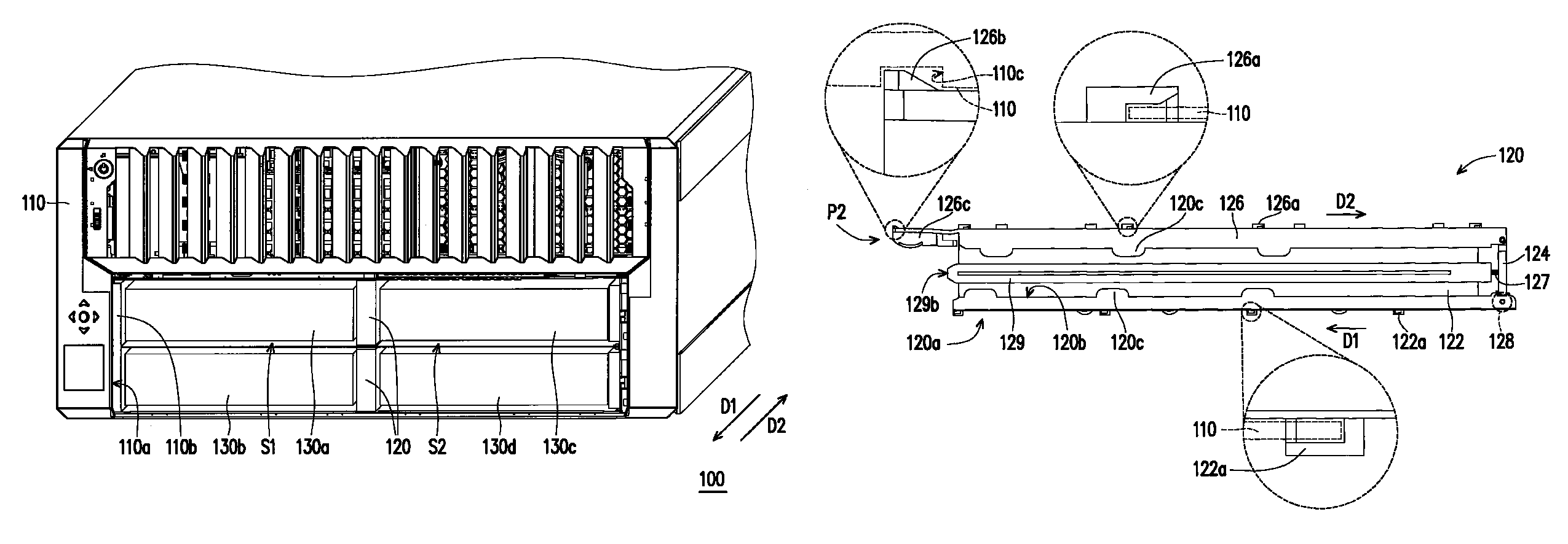
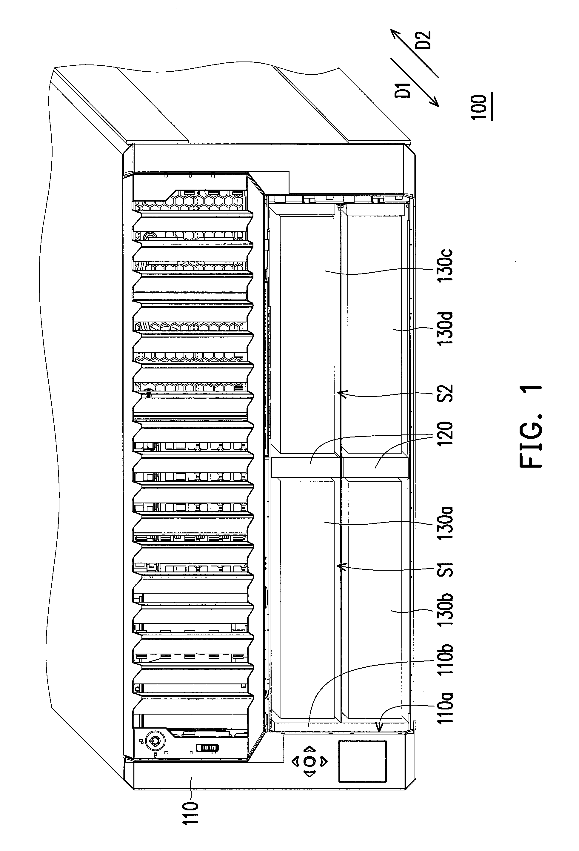
[0031]FIG. 1 is a partial three-dimensional view of a server according to an embodiment of the invention. Referring to FIG. 1, a server 100 of the present embodiment is, for example, a blade server, and includes a chassis 110, at least one partition 120 (two are illustrated), and at least one server unit (four are illustrated and labeled as 130a-130d). The chassis 110 has an accommodating cavity 110a. The partition 120 is configured to define a first space S1 and a second space S2 in the accommodating cavity 110a. The server units 130a-130d are arranged in the first space 51 or the second space S2 in the accommodating cavity 110a. It should be noted that the partition 120 is only schematically illustrated in FIG. 1 and a detailed structure thereof is not illustrated. The detailed structure of the partition 120 is described hereinafter with reference to FIG. 2 and FIG. 3.

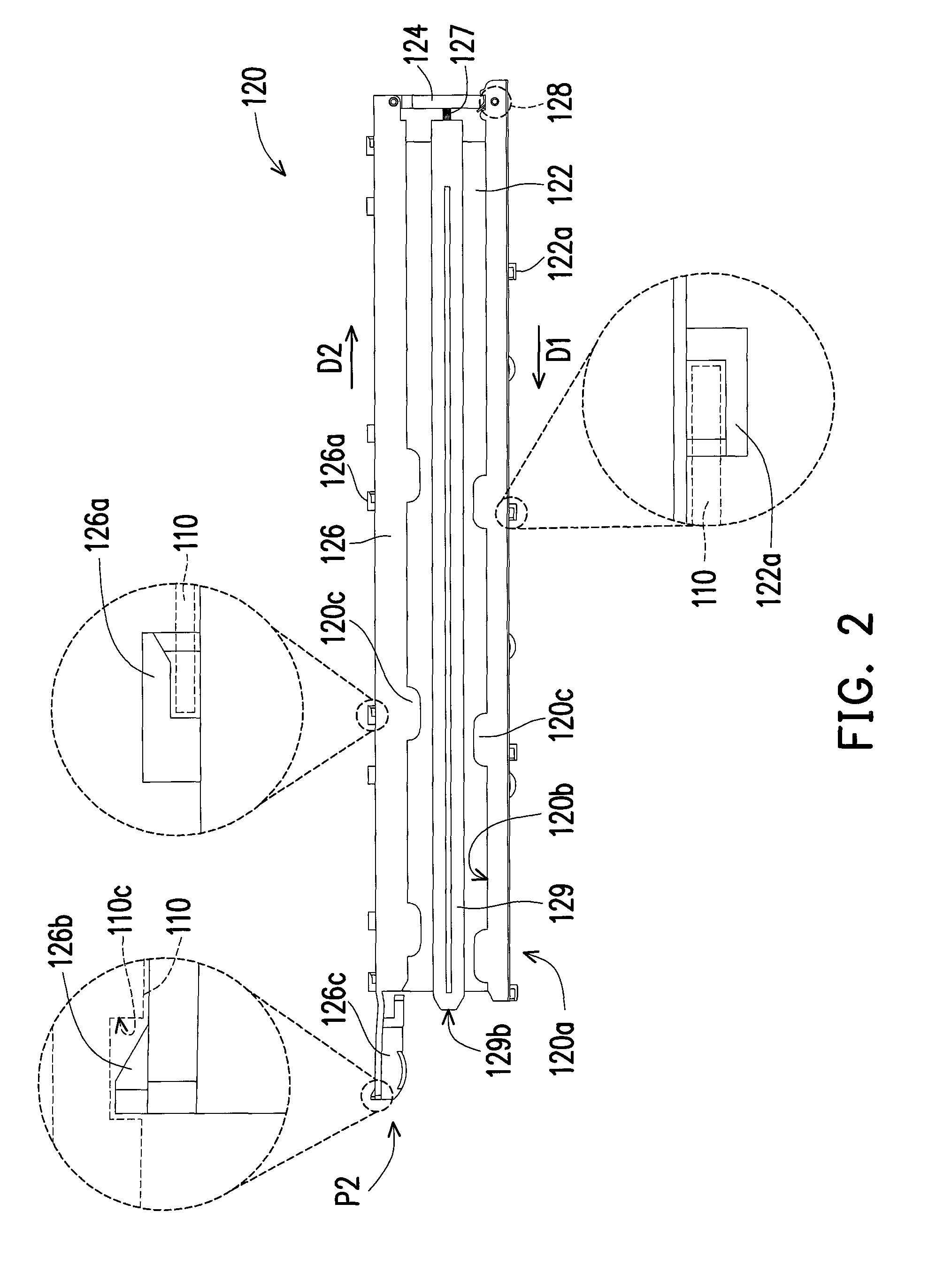
[0032]FIG. 2 is a side view of the partition in FIG. 1. FIG. 3 illustrates the partition in FIG. 2 in a not yet as...


PUM


Abstract

A server includes a chassis, at least a partition and at least a server unit. The chassis has an accommodating cavity and a first fixing structure. The partition has a second fixing structure and includes a plate, a pivot component and a locking component. A first space and a second space are defined in the accommodating cavity by the plate. The locking component has at least a first locking portion and a stopping portion. The pivot component is pivoted between the plate and the locking component. When the locking component moves from a first position to a second position, the first locking portion is locked to the chassis and the locking component is positioned by a structural interference between the stopping portion and the chassis. The server unit is fixed in the first space by the first fixing structure or fixed in the second space by the second fixing structure.

Description

CROSS-REFERENCE TO RELATED APPLICATION[0001]This application claims the priority benefit of Taiwan application serial no. 102102388, filed on Jan. 22, 2013. The entirety of the above-mentioned patent application is hereby incorporated by reference herein and made a part of this specification.FIELD OF THE INVENTION[0002]The invention relates to an electronic equipment and a partition thereof, and more particularly, to a server and a partition thereof.DESCRIPTION OF RELATED ART[0003]A so-called blade server is a server integrating hardware of a server system such as processor, memory, and even hard drive into a single motherboard as server units. The blade server also allows several server units to share a chassis, a power supply or other resources with each other, thereby lowering spatial requirements of the server. Since the blade server has the above advantage of saving arrangement space, manufacturers have been attracted to invest in development of such products.[0004]In detail, g...

Claims


Application Information

Patent Timeline
Patent Type & Authority Patents(United States)
IPC IPC(8): H05K5/00H05K7/14E04G3/00A47B96/06
CPCH05K7/1489
Inventor CHANG, CHIA-MING
Owner WISTRON CORP
Learn More