
LED lighting system

a technology of led lighting and led modules, applied in the direction of lighting apparatus, light sources, electrical equipment, etc., can solve the problems of not allowing the arrangement of more than one led module, the existing led lighting system is rather complex, and the requirement of three wires, so as to achieve the effect of convenient installation and easy manufactur

Active Publication Date: 2018-05-22
KONINK PHILIPS ELECTRONICS NV
View PDF7 Cites 1 Cited by
  • Summary
  • Abstract
  • Description
  • Claims
  • Application Information

AI Technical Summary

Benefits of technology

[0007]The invention aims to provide a less complex LED lighting system, that is easier to manufacture and also easier to install and that allows both series and parallel arrangement of the LED modules to a single power supply circuit.

Problems solved by technology

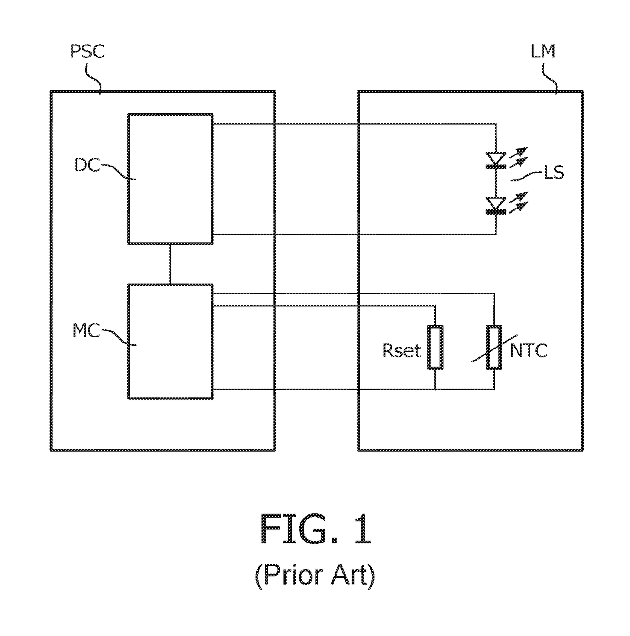
An important disadvantage of this prior art system and method is that three wires are required for connecting the resistors in the LED module with circuitry comprised in the power supply circuit.
This makes these existing LED lighting systems rather complex.
Furthermore, in case the LED lighting system comprises more than one LED module, this prior art does not allow more than one LED module to be arranged in series or in parallel according to the preference of a user.

Method used


Image

  • LED lighting system
  • LED lighting system
  • LED lighting system

Examples


Embodiment Construction

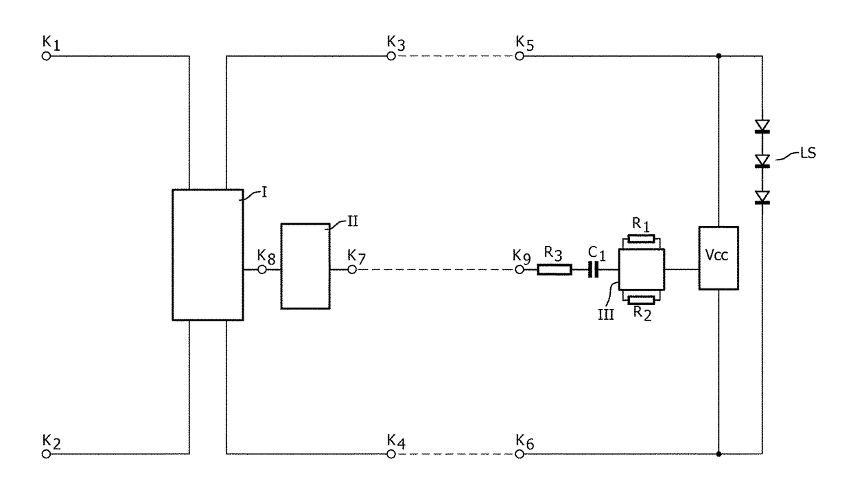
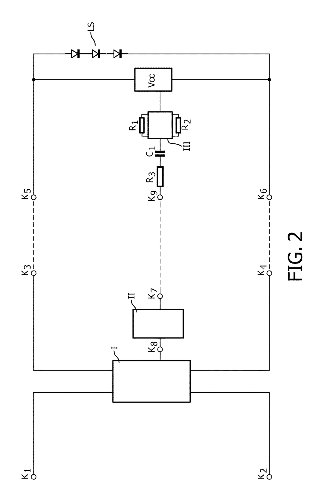
[0042]In FIG. 2, K1 and K2 are input terminals of a power supply circuit for connection to a supply voltage source. Input terminals K1 and K2 are connected to input terminals of circuit part I. First and second output terminals of circuit part I are connected to a first output terminal K3 and a second output terminal K4 of the power supply circuit respectively. Circuit part II is a driver control circuit. An output terminal K8 of circuit part II is coupled to an input terminal of circuit part I. Circuit part I and circuit part II together form a driver circuit for generating a LED current out of a supply voltage supplied by the supply voltage source. Circuit part II is equipped with an input terminal K7 for receiving a current control signal and for generating a LED current in dependency of the current control signal.

[0043]Terminals K5 and K6 are first and second input terminals of a LED module for connection to the first and second output terminals K3, K4 of the power supply circui...


PUM


Abstract

The invention relates to a LED lighting system comprising a power supply circuit and at least one LED module. The power supply circuit comprises input terminals (K1, K2) for connection to a supply voltage source and output terminals (K3, K4),and a driver circuit (I, II) coupled between the input terminals and the output terminals for generating a LED current out of a supply voltage supplied by the supply voltage source, and comprising a driver control circuit (II) with an input terminal (K7) for receiving a current control signal and for generating a LED current in dependency of the current control signal. The at least one LED module comprises input terminals (K5, K6) for coupling to the output terminals of the power supply circuit, a LED load (LS) coupled between the input terminals, and a module control circuit for generating a current control signal as a square wave shaped signal comprising a first part having a first amplitude during a first time lapse representing a desired magnitude of the LED current, said module control circuit comprising an AC coupling of the current control signal to the input terminal of the driver control circuit.

Description

CROSS-REFERENCE TO PRIOR APPLICATIONS[0001]This application is the U.S. National Phase application under 35 U.S.C. § 371 of International Application No. PCT / IB13 / 053298, filed on Apr. 26, 2013, which claims the benefit of U.S. Provisional Patent Application No. 61 / 643,976, filed on May 8, 2012 and European Patent Application No. 12167070.7 filed on May 8, 2012. These applications are hereby incorporated by reference herein.FIELD OF THE INVENTION[0002]The invention relates to a LED lighting system comprising a power supply circuit and one or more LED modules. More in particular the invention relates to a LED lighting system, wherein the power supply circuit adjusts the power supplied to the LEDs in the LED modules in dependency of signals generated by circuitry comprised in the LED modules, said signals in turn depending on the nominal power of the LEDs comprised in the LED module.BACKGROUND OF THE INVENTION[0003]Lighting systems based on LEDs are used on an increasing scale.[0004]L...

Claims


Application Information

Patent Timeline
Patent Type & Authority Patents(United States)
IPC IPC(8): H05B33/08H05B44/00
CPCH05B33/0854H05B33/083H05B33/0848H05B33/0827H05B33/089H05B45/14H05B45/56H05B45/46H05B45/48
Inventor RADERMACHER, HARALD JOSEF GUNTHERLULOFS, KLAAS JACOBDE WIT, LINO ADRIAAN NICOLAAS WILHELMDEURENBERG, PETER HUBERTUS FRANCISCUS
Owner KONINK PHILIPS ELECTRONICS NV
Learn More